

OPTICAL CABLE CLOSURE
Fiber Optic Splice Closure
(
VSOF-BS606G) User Manual
VISSEM VSOF--BS606G-Manual Rev.0 TEL: 031-288-3481 FAX: 031-283-7844
All rights reserved by VISSEM Electronics Co. Ltd.
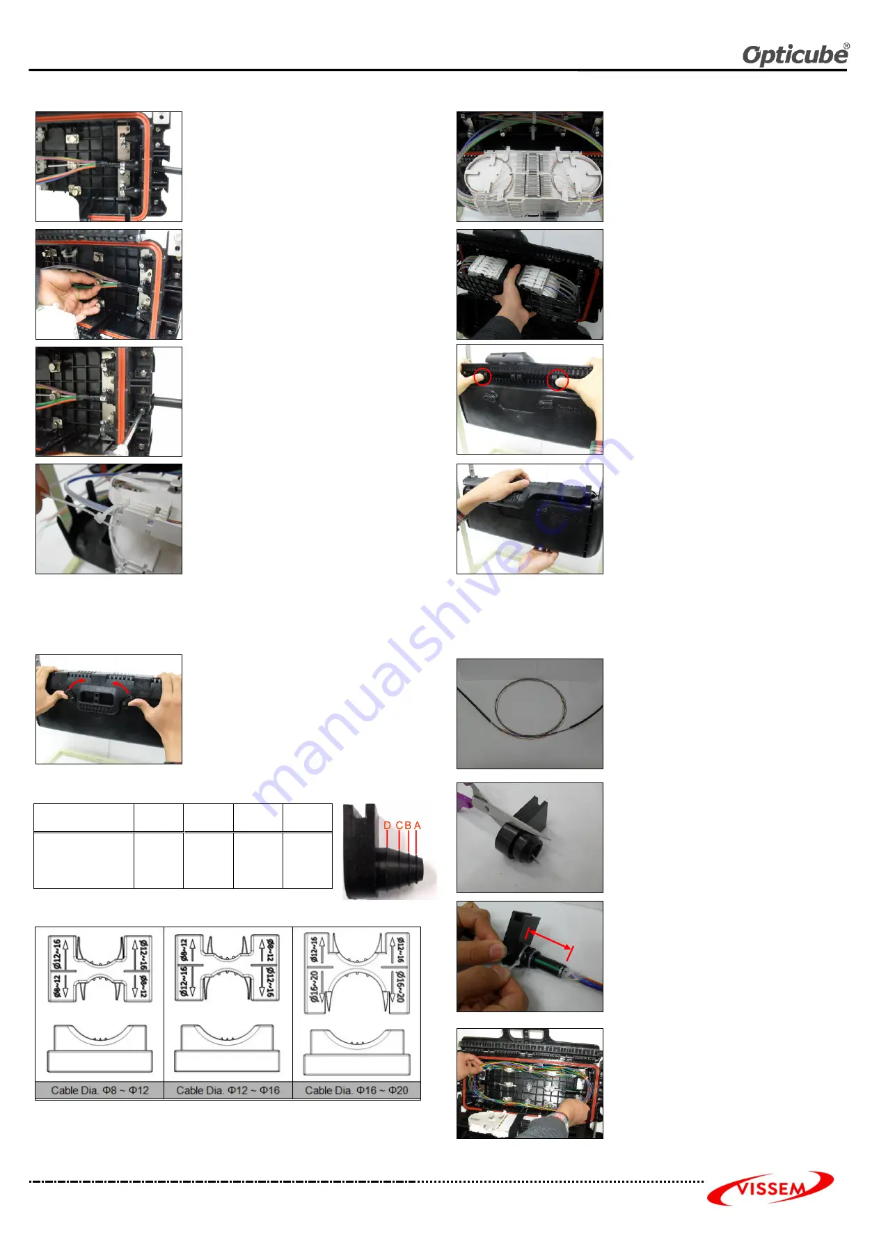
13. Inserting Cable
Insert the cable into the inside of closure.
Tension Member must pass through the hole of
T/M.
Cable sheath must pass through the center of Steel
band.
17. Splicing & Arranging cores
Splice fibers in accordance with splicing method
to be approved.
After the splice, insert the splice protection
sleeve in each slit accordingly.
Coil surplus fibers in the tray in a figure 8 shape.
After the arrangement, apply the O-ring into the
slit and close the tray lid.
14. Fixing Tension Member and Steel-Band
Tighten the steel-band by using screwdriver with
proper strength to fix the cable.
Tighten the T/M Nut by using hand or coin with
proper strength to fix the Tension Member.
18. Tie Tray Band and Fixing Tray-
Supporter
Tie the splice trays by using splice tray band to
be provided.
And Fix the Tray-Supporter at lower main body
by using hock.
15. Fixing Sheath Holder
Select a Sheath Holder (Top) appropriate to the
diameter of the cable. Afterward fix the cable
Sheath by using screwdriver.
* Do not over-tighten the bolt, as Cable can be
damaged.
* Standard for selection of Sheath Holder (top):
Refer to page 7.
19. Assembling the Clip Handle (1)
Bend back Clip Handle as much as possible.
Push the A part of Upper Cover by using your
thumb as shown in figure and rotate the Clip
Handle direction down the closure.
A part of Upper Cover is entered inside Clip
Handle.
16. Fixing Unit Protection Tube
Open the tray lid.
Insert the Unit Protection Tube into the inlet on the
splice tray and fix the Unit Protection Tube by using
cable ties.
Cut the remaining cable ties and Arrange Unit
Protection Tube with Unit Tube Guide.
20. Assembling the Clip Handle (2)
Push front of Clip-Handle until there is a sound
such as clack.
*
Be careful about that your finger is caught
between clip handle and upper cover.
* Check the locking levers to be horizontal to the
ground before you close the Clip Handle.
5
6
7
8
◈
◈
◈
◈
Installation Instruction for mid span branching
25. Rotating Locking Lever
Rotate the each Locking Lever inside 90 degree as
shown in figure.
1. Cable Preparation
Remove 3m of the cable sheath using a sheath
stripper.
Remove plastic tape and dummy filler tube.
Cut Tension member 10cm from the Cutting
Plane.
* Be careful not to cut loose tube.
◈
◈
◈
◈
Cutting position according to the diameter of the cable for installation
mid span branching
Cutting line
A
B
C
D
Cable Dia. (Φ)
8mm
9mm
~
13mm
13mm
~
17mm
17mm
~
20mm
2. Cutting Sheath Gasket
Cut the cone of Sheath Gasket.
Cut off one side of sheath gasket.
Apply the high vacuum grease on the cable for
excellent water-proof.
* Cutting position of Sheath Gasket: Refer to
page 7.
3. Fixing Cable and Insertion Cable
Fix the cone of gasket by using cable tie or tape.
Put the gasket on the entry of the closure. Fix the
cable through T/M, Steel-band and Sheath
Holder.
◈
◈
◈
◈
Application method of Sheath Holder according to the diameter of cable
※
Application method of M5 bolt for fixing the Sheath Holder
▶
Sheath Holder(Φ8~16): Length 30
▶
Sheath Holder(Φ12~20): Length 40
4. Arranging Loose Tube
Arrange the loose tube into the closure as using
Tube Guide
5cm
A
A


