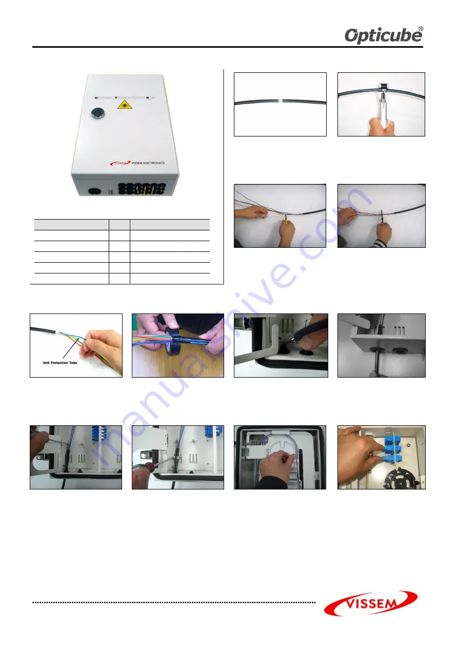
OPTICAL TERMINATION BOX
VSOF-OTB-E Manual
VISSEM OTB-E Manual Rev.0 TEL: 82-31-283-7852 FAX: 82-31-283-7844
All rights reserved by VISSEM Electronics Co. Ltd.
1. Marking a Cutting Point
Mark a sheath removing point on the cable
with a piece of tape at a 100cm point from
the cable cut end.
2. Sheath Removing
Remove the cable sheath from the
marked point by using a sheath stripper
Remove all plastic tape.
Component List
Items
Unit
Q’ty
Protection Tube
EA
2 X Splice Tray
Heat shrinkable sleeve
EA
Number of cores
Key Lock
EA
2
Cable tie
EA
4 X Splice Tray
Cord Protection Tube
EA
4 X Splice Tray
3. Cutting Tension Member
Leave 6cm from the cable and cut off the
tension me mber.
4. Removing Loose Tubes
Leave about 4cm from the cable sheath
end and remove the rest of the loose
tube.
Clean the cut area by using jelly cleaner.
Note. Be sure not to damage the fiber
optics.
5. Inserting Unit Protection Tube
Insert fibers into the unit protection tubes
carefully all the way up to the point where
loose tubes end.
Wrap the tape around the end point of
protection tube at cable side.
6. Cutting Sheath Gasket
Check the outer diameter of the cable and
cut off the sheath gasket according to the
cable diameter marked on it.
7. Inserting Fiber Optic Cable
Check the outer diameter of the cable
and cut off the sheath gasket according
to the cable diameter marked on it.
8. Fixing Fiber Optic Cable
Insert the tension me mber into the T/M
fixing bracket and tighten them together
by using a screwdriver
Secure the cable to the center of the
Susband Bracket by using a susband
9. Routing Protection Tube
Route protection tubes to the splice tray
inlet and secure the protection tubes on
the splice tray inlet by using cable tie.
10. Pigtail Connection
Connect the pigtails to the adapters by
turns on the adapter panel.


