background image


12. SERVICING        

 Do not attempt to service the video monitor or equipment yourself as opening or 
removing covers may expose you to dangerous voltage or other hazards.   


Refer all servicing to qualified service personnel. 

13. DAMAGE REQUIRING SERVICE 

Unplug the equipment from the wall outlet and refer servicing to qualified service 
personnel under the Following conditions: 


A.

 When the power supply cord or the plug has been damaged.       


B.

 If liquid has spilled or objects have fallen into the Unit.       

      C.

 If the equipment has been exposed to water or other liquids. 

D.

 If the equipment does not operate normally by following the operating 

instructions, adjust those controls that are covered by the operating instructions as  
Improper adjustment for other controls may result in damage to the unit.   


E.

 If the equipment has been dropped or the casing is damaged.       


F.

 When the equipment exhibits a distinct change in performance.    

14. REPLACEMENT PARTS       

When replacement parts are required, be sure the service technician uses 
replacement parts specified by the manufacturer or that have the same 
characteristics as the original part. 

      Unauthorized substitutions may result in fire, electric shock, or other hazards. 

15. SAFETY CHECK 

Upon completion of any service or repairs to the equipment, ask the service 
technician to perform safety checks to verify that the equipment is in proper 
operating condition. 

16. FIELD INSTALLATION 

The installation of equipment should be made by a qualified service person and 
should conform to all local codes. 

17. CAUTION  


THESE SERVICING INSTRUCTIONS ARE FOR USE BY QUALIFIED SERVICE   

PERSONNEL ONLY. TO REDUCE THE RISK OF ELECTRIC SHOCK DO NOT 
PERFORM ANY SERVICING OTHER THAN THAT CONTAINED IN THE 
OPERATING INSTRUCTIONS UNLESS YOU ARE QUALIFIED TO DO SO. 

18.

 Use certified/Listed Class 2 power source only. 


CE COMPLIANCE STATEMENT   


WARNING 

This is a Class A product. In a domestic environment this product 
may cause radio interference in which case the user may be required 
to take adequate measures. 

Summary of Contents for VVRD28V12CM760H

Page 1: ...Set up and user manual for the VVRD28V12CM760H VVRD28V12DN760H VVRD28V12DNLED760H Cameras Installation Manual MManualManual...

Page 2: ...1...

Page 3: ...ting maintaining and troubleshooting this product refer to this document and any other documentation provided If you still have questions please contact Norbain Technical Support and Sales Vista 210 W...

Page 4: ...eled bin mark symbolizes that within the European Union the product must be collected separately at the product end of life This applies to your product and any peripherals marked with this symbol Do...

Page 5: ...pplied at the installation location contact your dealer For equipment designed to operate from battery power refer to the operating instructions 8 GROUNDING OR POLARIZATION Equipment that is powered t...

Page 6: ...rmance 14 REPLACEMENT PARTS When replacement parts are required be sure the service technician uses replacement parts specified by the manufacturer or that have the same characteristics as the origina...

Page 7: ...6 TABLE OF CONTENTS INTRODUCTION 7 CONTENTS OF PACKAGE 8 BASIC INSTALLATION 8 TACT SWITCH OPERATION SERVICE JACK 9 OSD MENU STRUCTURE 10 LENS ADJUSTMENT 16 DIMENSIONS 17 SPECIFICATIONS 18...

Page 8: ...rage from 16 x 850nm LEDs DNLED model only OSD On Screen Display via tact switch D WDR Digital Wide Dynamic Range BLC Back Light Compensation HBLC Highlight Back Light Compensation Peak White Inversio...

Page 9: ...mplate as a drilling guide to ensure correct positioning of the screws 3 Drill 4 holes into the mounting template Insert the screw raw plugs anchors and attach the housing using the 4 x M6 Torx screws...

Page 10: ...and navigate using the up down left and right actions If there is an arrow to the right of the menu function this denotes that there is an accessible sub menu function The white 2 pin plug to the lef...

Page 11: ...DWDR AGC 2D DNR DAY NIGHT AUTO COLOUR B W EX CDS FUNCTION MIRROR SHARPNESS MONITOR GAMMA LSC RETURN PRIVACY MASK 1 8 COLOUR WB MODE R Y GAIN B Y GAIN SET UP TITLE MANUAL DPC AUTO DPC OLPF OSD COLOUR R...

Page 12: ...Manual setting allows you to adjust a single area in size and location to apply BLC to the image BLC Weight Off Low Mid High HLI Peak White Inversion HBLC Applies BLC to a single user definable area t...

Page 13: ...ode ATW Manual AWC Push AWC Adjusts the white balance to suit area being viewed Manual Allows you to adjust the Red and Blue content of the image M WB R 0 128 increments of 1 M WB B 0 128 increments o...

Page 14: ...me or switching level C_Sup 0 to 100 increments of 1 Adjusts the colour noise in a low light image 0 unsuppressed 100 full suppression A_Sup 0 to 100 increments of 1 Adjusts the Aperture to assist wit...

Page 15: ...as no effect PRIVACY PRIVACY allows upto 8 masks to be applied to the image Mask1 8 Off On Dot Sel L_TOP L_BOT R_BOT R_TOP Moves cursor to that location on the privacy mask Dot XY Pushing enter on tac...

Page 16: ...ht to pass NOTE whilst in the OSD menu and adjustable these settings will have no effect on the camera image OSD Colour Choose from the following colours for the OSD Grey black white red green blue ma...

Page 17: ...click enter on the tact switch then Save Exit LENS ADJUSTMENT Field of view Adjust setting from Tele T to Wide W field of View Focus Adjust lens focus from near N to infinity 2 8 to 12mm Image Size 1...

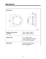
Page 18: ...17 DIMENSIONS...

Page 19: ...urst Off On Mot Detection 4 areas Privacy Zones 8 zones with 8 selectable colours White Balance ATW Manual AWC Push AWC AGC Off Low Mid High 2D DNR Off Low Mid High Monitor Mode 1 CRT Mode 2 LCD DPC O...

Page 20: ...19 VVRD28V12 760H Manual V1 2013 05 10 This manual is subject to change without notice...

Reviews: