background image

2

INTRODUCTION

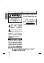
WARNING : TO REDUCE THE RISK OF FIRE OR ELECTRIC SHOCK,

DO NOT EXPOSE THIS PRODUCT TO RAIN OR MOISTURE.

If you pour a cold liquid into a glass, water vapor
in the air will condense on the surface of the
glass. This is moisture condensation. Moisture
condensation on the head drum, one of the most
crucial parts of the unit, will cause  damage to the
tape.
When the VCR is exposed to a rapid temperature
change from cold to warm, some condensation
will occur. Under this condition, connect the power
cord to the AC line, press 

POWER

button on and

allow at least two hours for the VCR to dry out.

MOISTURE CONDENSATION

RISK OF ELECTRIC SHOCK

DO NOT OPEN

CAUTION

CAUTION : TO REDUCE THE RISK

OF ELECTRIC SHOCK,

DO NOT REMOVE COVER (OR BACK);

NO USER-SERVICEABLE PARTS INSIDE

REFER SERVICING TO QUALIFIED SERVICE

PERSONNEL.

The serial number is found on the back of this
unit. This number is unique to this unit and not
available to others. You should record requested
information here and retain this guide as a per-
manent record of your purchase.

Model No. 

VVRL-960

Serial No. 

CAUTION :

TO  PREVENT ELECTRIC SHOCK,

DO NOT USE THIS PLUG WITH AN EXTEN-
SION CORD, RECEPTACLE OR OTHER OUT-
LET UNLESS THE PLUG CAN BE FULLY
INSERTED WITHOUT EXPOSING ANY PARTS
OF THE BLADES.

This lightning flash with arrowhead sym-
bol within an equilateral triangle is intend-
ed to alert the user to the presence of
uninsulated dangerous voltage within the
product’s enclosure that may be of suffi-
cient magnitude to constitute a risk of
electric shock to persons.

The exclamation point within an equilater-
al triangle is intended to alert the user to
the presence of important operating and
maintenance (servicing) instructions in the
literature accompanying the product. 

IMPORTANT COPYRIGHT INFORMATION: 

Many

television programs and films are copyrighted. In
certain circumstances, copyright law may apply to
private in-home video taping of copyrighted materi-
als.

Warning : This is a class A product . In a domestic enviroment this product 

may cause radio interference in which case the user may be 
required to take adequate measures.

Summary of Contents for VVRL-960

Page 1: ...FORMATION V S T A I TIME LAPSE VCR OWNER S MANUAL MODEL VVRL 960 Before connecting operating or adjusting this product please read this instruction booklet carefully and completely REV PLAY P STILL PLAY REC CHECK POWER REC STOP EJECT ALARM KEY R E W F F LOCK ...

Page 2: ...cord requested information here and retain this guide as a per manent record of your purchase Model No VVRL 960 Serial No CAUTION TO PREVENT ELECTRIC SHOCK DO NOT USE THIS PLUG WITH AN EXTEN SION CORD RECEPTACLE OR OTHER OUT LET UNLESS THE PLUG CAN BE FULLY INSERTED WITHOUT EXPOSING ANY PARTS OF THE BLADES This lightning flash with arrowhead sym bol within an equilateral triangle is intend ed to a...

Page 3: ...eck the Power Fail recall 26 Keyboard Lock On Off Switch 26 Self Diagnosis 27 Service Guide Table 28 VIDEO Head Cleaning 28 Troubleshooting 29 Specifications 30 RC 232C PROTOCOL 31 45 Time Lapse VCR Function Trigger Function Buzzer Function Auto Switcher used possible Tape compatibility Elapsed time display Series Recording Function Alarm Recording Function INTRODUCTION This unit is a part of the ...

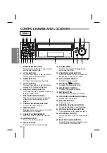
Page 4: ...ive and deactivate toggle the alarm index function 13 COUNTER CLEAR BUTTON To set the counter to zero or erase the information on the menu screen 14 LOCK ON OFF SWITCH To switch lock and unlock 15 TRACKING E E D D BUTTON To adjust the manual tracking 16 SHARPNESS CONTROL To adjust the playback quality 17 ENTER BUTTON To select items on the menu screen 18 VCR FUNCTION INDICATOR PANEL Details are in...

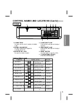
Page 5: ...ntil any key is pressed VOH 4 5V VOL 0 0 6V T above 8 10msec VOH 4 5V VOL 0 0 6V T below 5 min end of tape VIH 4 5V VIL 0 0 6V T above 250msec 0V 1 POWER CORD Connect only to an AC 100 240V 50 60Hz outlet 2 RS232C CONNECTOR Connect a personal computer for controlling the VCR 3 MONITOR OUT JACK Connect to another monitor 4 AUDIO IN OUT JACK Connect the audio input and output terminal 5 VIDEO IN OUT...

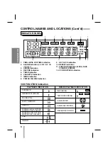
Page 6: ...tion 9 KEY LOCK indication 10 REPEAT Indication 11 FUNCTION Indication CLOCK TAPE COUNTER ERROR 12 VCR FUNCTION Indication VCR FUNCTION Indication PLAYBACK INDICATION BESIDE PLAYBACK INDICATION PLAYBACK REVERSE PLAYBACK PAUSE STILL FAST FORWARD REWIND CUE REVIEW RECORDING TIMER RECORDING ALARM INDEX ALARM RECORDING SERIES RECORDING FORWARD SLOW PICTURE FORWARD FIELD ADVANCE REVERSE SLOW PICTURE RE...

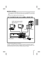
Page 7: ...s please change the MONITOR of TV with A V input jack Connect the CCD CAMERA to VCR s VIDEO input jack RS 232C communication is possible when the optional RS 232C interface adaptor is mounted RS 232C is an interface standard for data terminals and data communications equipment employing serial binary data exchange as stipulated under the RS 232 CCIR standard Using the RS 232C interface this VCR ca...

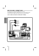
Page 8: ...CHER WITH TRIGGER INPUT TERMINAL If the switcher has two output terminals MONITOR OUT PB OUT connect MONITOR to the PB OUT terminal when you want to see the playback picture To use the switcher and trigger function properly refer to their instruction booklet ...

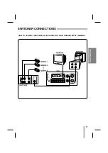
Page 9: ...9 PREPARATION SWITCHER CONNECTIONS HOW TO CONNECT SWITCHER WHICH DOES NOT HAVE TRIGGER INPUT TERMINAL ...

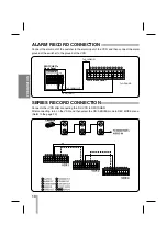
Page 10: ...T To ALARM IN To GROUND To GROUND ALARM RECORD CONNECTION Connect the alarm out of the switcher to the alarm input of the VCR and then connect the alarm ground of the switcher to the ground of the VCR Connect other VCR after connecting the first VCR to SWITCHER After connecting turn on the VCR and then select the ON SERIES mode in REC MODE menu Refer to the page 22 ...

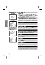
Page 11: ...NTER button VCR SET UP G CLOCK SET ELAPSED TIME VHS TAPE E 180 VIDEO COLOR DISPLAY ON AUDIO PLAY ON QUASI V SYNC ON UP DOWN ENTER MENU REC MODE G REC TIME 000H INTERVAL 10SEC TRIGGER OUT 1 FIELD SERIES OFF REPEAT OPTION STOP AT EOT UP DOWN ENTER MENU ALARM SET UP G REC MODE 6H DURATION 1 MIN BUZZER ON ALARM READY ON ALARM RECALL UP DOWN ENTER MENU POWER FAIL RECALL G1 OFF 01 01 00 20 56 55 ON 01 0...

Page 12: ... of both the VCR and the MONITOR If you have a TV instead of MONITOR turn on the power of TV and then set the TV s source selector to VIDEO 1 Press MENU button The main menu will appear Press DOWN or UP button to choose the VCR SET UP 2 Press ENTER button The VCR SET UP menu will appear VCR SET UP G CLOCK SET ELAPSED TIME VHS TAPE E 180 VIDEO COLOR DISPLAY ON AUDIO PLAY ON QUASI V SYNC OFF UP DOWN...

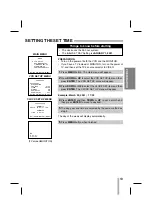
Page 13: ...ss ENTER The VCR SET UP menu will appear 3 Press DOWN or UP to select the CLOCK SET item and then press ENTER The CLOCK SET UP menu will appear 4 Press ENTER and then DOWN or UP to set a month and then press ENTER to move to day item 5 The day year and time are selected by the same method as step 4 6 Press MENU button when finished Things to know before starting 12H 17 30 01 11 20 00 VCR SET UP G ...

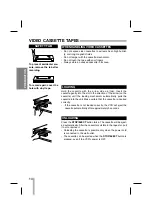
Page 14: ...ain that the cassette is inserted correctly If the cassette is not loaded correctly the VCR will eject the cassette automatically after approximately 3 seconds Press the STOP EJECT button twice The cassette will be eject ed automatically After the cassette is visible in the tape slot pull it out to remove it Unloading the cassette is possible only when the power cord is connected to the wall outle...

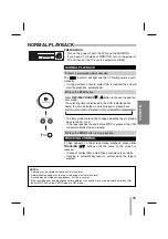
Page 15: ...efully Tracking is automatically reset to normal when the tape is ejected TRACKING CONTROL NORMAL PLAYBACK 1 Insert a prerecorded video cassette 2 Press the PLAY button 3 Press the STOP button to stop playback PLAYBACK PREPARATION Turn on the power of both the VCR and the MONITOR If you have a TV instead of MONITOR turn on the power of TV and then set the TV s source selector to VIDEO REV PLAY P S...

Page 16: ...e called REVIEW During PLAYBACK mode The VCR will be activated in the CUE or REVIEW mode If the VCR is left in the CUE or REVIEW mode for more than 3 minutes the VCR will automatically enter the PLAY mode to protect the tape and video heads TO WATCH A REVERSE PLAYBACK PICTURE 1 Press the P STILL button 2 To continue normal playback press the PLAY button 1 Rotate and release the SHUTTLE ring to tow...

Page 17: ...D D E E buttons can be used to minimize noise bands If the VCR is left in the forward slow mode for more than 3 minutes reverse slow 30 seconds the VCR will automati cally enter the PLAY mode to protect the tape and video heads During STOP mode The INDEX indicator will appear in the VCR indicator panel Play for 5 seconds when detected alarm recording part and then searched to the next alarm record...

Page 18: ... This function is only provided in COUNTER displayed in the VCR indicator panel Continue to play or record The VCR will stop at the COUNTER position 0 00 00 COUNTER MEMORY FUNCTION REAL TIME COUNTER Press the TIME CNT REM button 1 Begin recording or playing a tape 2 At the point where you want to playback to begin reset the real time counter to 0 00 00 by pressing the COUNTER CLEAR button 3 Press ...

Page 19: ... REC CHECK POWER REC STOP EJECT ALARM KEY R E W F F LOCK V POS H POS FIELD ADVANCE TIME CNT REM TIMER REC PLAY HOURS ALARM INDEX MENU COUNTER ENTER CLEAR LOCK SHARPNESS ON OFF SOFT HARD TRACKING CURSOR DOWN UP REC MODE G REC TIME 3H TRIGGER OUT 1 FIELD SERIES OFF REPEAT OPTION STOP AT EOT UP DOWN ENTER MENU REC MODE REC TIME 000H G INTERVAL 10SEC TRIGGER OUT 1 FIELD SERIES OFF REPEAT OPTION STOP A...

Page 20: ...ise the tape will be automatically ejected Turn on the power of both the VCR and the MONITOR Things to know before starting 1 Press MENU button and the main menu will appear 4 Press MENU when finished And press MENU repeatedly to exit menu screen 5 Press REC button The VCR will start recording REV PLAY P STILL PLAY REC CHECK POWER REC STOP EJECT ALARM KEY R E W F F LOCK V POS H POS FIELD ADVANCE T...

Page 21: ...imer Recording only when the SET item set to ON 5 Press ENTER to select next item and then set the next items day start time end time recording hour by using UP DOWN and ENTER buttons MAIN MENU TIMER REC MODE MENU REV PLAY P STILL PLAY REC CHECK POWER REC STOP EJECT ALARM KEY R E W F F LOCK V POS H POS FIELD ADVANCE TIME CNT REM TIMER REC PLAY HOURS ALARM INDEX MENU COUNTER ENTER CLEAR LOCK SHARPN...

Page 22: ... starting 1 Press MENU button and the main menu will appear 2 Press UP or DOWN button to choose the REC MODE SET UP item and then press ENTER 3 Press the UP or DOWN button to choose the SERIES item Press ENTER to choose ON 4 Press MENU when finished And press MENU repeatedly to exit menu screen 5 Press REC button The first VCR will start recording REV PLAY P STILL PLAY REC CHECK POWER REC STOP EJE...

Page 23: ...is in place Things to know before starting 1 Press MENU and the main menu will appear 2 Press the DOWN or UP button to choose the ALARM SET UP item then press ENTER 3 Press the DOWN or UP button to choose the REC MODE item And press repeatedly ENTER to choose recording hours ALARM SET UP 4 Press the DOWN button to choose the DURATION item And press repeatedly ENTER to choose the desired duration o...

Page 24: ... ON 3H 12H 24H the ALARM indicator will light in VCR indicator panel ALARM indicator in VCR indicator panel are blink when the alarm recording is proceeding For example When the Alarm REC MODE is set to 3H 5 Press the DOWN to choose the BUZZER item And press repeatedly ENTER to switch buzzer function during alarm recording 6 Press the DOWN to choose the ALARM READY item And press repeatedly ENTER ...

Page 25: ... repeatedly to exit menu screen NOTES Alarm history can be memorized up to 16 alarms but only 8 can be displayed on the MONITOR Press DOWN button repeatedly to see the next page If you want to erase the alarm history please press the CLEAR button To erase the alarm history ALARM RECALL 1 01 01 00 00 21 13 G 2 01 02 00 04 07 37 3 01 03 00 03 59 36 4 5 6 7 8 DOWN CLEAR MENU ALARM REC MODE MENU MAIN ...

Page 26: ...press the CLEAR button The power fail recall is erased To erase the power fail recall MENU VCR SET UP REC MODE SET UP TIMER REC SET UP ALARM SET UP G POWER FAIL RECALL UP DOWN ENTER MENU POWER FAIL RECALL 1 OFF 01 01 01 20 56 55 ON 01 01 01 24 00 00 G2 OFF 03 15 01 12 25 50 ON 03 15 01 16 56 53 3 OFF ON 4 OFF ON DOWN CLEAR MENU To protect unpermitted person s using select LOCK switch to ON Other b...

Page 27: ... 6 seconds aftercassetteloadingattempt Mode Switch Position not changed within 6 seconds aftercassetteloadingattempt CST Switch must be activat ed within 3 seconds other wise unit shut down will occur CFG Signal present but take up pulses are missing Capstan motor running Drum Motor Slow Start Motor must be up to speed within 3 seconds of operation Loading Motor Drive IC Loading Motor Mode Switch ...

Page 28: ...ning Checking Notes Check the running path adjustment when you change the 1 3 5 6 and 10 item Check the back tension when you change Band Assy Tension VIDEO HEAD CLEANING It is possible that the heads may become clogged when playing an old or damaged tape If your picture play back quality deteriorates the heads may need cleaning To clean the heads obtain a head cleaning tape from your local video ...

Page 29: ... Stick a piece of cellophane tape over the erase prevention tab hole or select a different cassette Insert a cassette Cassette cannot be inserted The VCR will not go into the recording mode even when REC button is pressed No picture appears on monitor screen when PLAY button is pressed No picture but audio is clear Interference on playback picture VCR does not start at preset record starting time ...

Page 30: ...cording Time 3 hours E 180 3H 15 hours E 180 12H 27 hours E 180 24H 48H 960H Tape Width 12 7 mm Rewind Time About 65 seconds E 180 Video Signal System CCIR Standard 625 lines 50 fields PAL type color signal Video Input 1 0 Vp p 75 ohms unbalanced Video Output 1 0 Vp p 75 ohms unbalanced Signal to Noise Ratio More than 43 dB 3H mode Conventional audio Input LINE 6 0 dBm more than 47 kohms Output LI...

Page 31: ...31 RS 232C PROTOCOL ...
Page 32: ...command again about 100ms at minimum If you send another command before 100ms VCR may not answer the command 2 TXD 3 RXD 4 RTS 5 CTS 6 DSR 7 GND 2 TXD 3 RXD 4 5 6 10V 7 GND 2 TXD 3 RXD 4 RTS 5 CTS 6 DSR 7 GND 2 TXD 3 RXD 4 5 6 10V 7 GND PIN number Name Description Direction 2 TXD Transmitted Data computer VCR 3 RXD Transmitted Data computer VCR 4 RTS Request to Send 5 CTS Clear To Send 6 DSR Data ...

Page 33: ...ice means VCR receive the command correctly but VCR do not service the received command because of VCR s internal status or mode KPON End of TX character ASCII code 29H Command capital letters ASCII codes Start of TX character ASCII code 28H Error code number description 1 31H Undefined Command 2 32H Parity Error 3 33H Frame Error 4 34H Overrun Error 5 35H No Service ...

Page 34: ...F 46h means HEX data F fh represents a number this number is ASCII code ASCII code 0 30h means a number 0 3 All commands are consist with capital letters All commands are case sensitive 4 All setting command include clear command do not function when VCR is now servicing Alarm record timer record or OSD menu service 5 VVRL 960 time lapse VCR can return an error code see TABLE 3 Error Code for deta...

Page 35: ...ame function as REV PLAY button Reverse play the tape POWER ON KPON KPON Do the same function as POWER button when VCR turn off Turn on the VCR POWER OFF KPOF KPOF Do the same function as POWER button when VCR turn on Turn off the VCR TIMER KTMR KTMR Do the same function as TIMER button Set the VCR as a TIMER mode H POSITION KHPS KHPS Do the same function as H POS button Adjust F OSD display posit...

Page 36: ...1001 RECORD PAUSE 01010 FIELD ADVANCE 01011 CUE 01100 REVIEW 01101 STILL 01110 SLOW 01111 REVERSE SLOW 10000 DECK MALFUNCTION 10001 RESERVED 10010 RECORD CHECK 10011 REVERSE FIELD ADVANCE 10100 ALARM RECORD 10101 TIMER RECORD 10110 INDEX SEARCH FORWORD 10111 INDEX SEARCH REVERSE 11000 INDEX PLAY VCR INFORMATION QINF QINF Query informations appear in the FPD Front Panel Display on the VCR 1 byte da...

Page 37: ...99 VHS TAPE SETTING QVHS QVHS Query current VHS TAPE setting If E 180 QVHS180 If E 240 QVHS240 If E 260 QVHS260 If E 300 QVHS300 VIDEO OPTION QVID Query current VIDEO option setting SETTING QVIDC If VIDEO option is COLOR QVIDC QVIDB If VIDEO option is BLACK WHITE QVIDB DISPLAY OPTION QDSP Query current DISPLAY ON OFF option SETTING QDSPON If DISPLAY option is ON QDSPON QDSPOFF If DISPLAY option is...

Page 38: ...SDSPON Set current DISPLAY ON OFF option SETTING SDSPOFF SDSPOFF If DISPLAY option is ON SDSPON If DISPLAY option is OFF SDSPOFF AUDIO PLAY SAUDON SAUDON Set current AUDIO PLAY ON OFF option OPTION SETTING SAUDOFF SAUDOFF If AUDIO PLAY option is ON SAUDON If AUDIO PLAY option is OFF SAUDOFF QUASI VSYNC SVSYON SVSYON Set QUASI VSYNC option OPTION SETTING SVSYOFF SVSYOFF If QUASI VSYNC option is ON ...

Page 39: ...tion RQSRON If Series option is ON RQSRON RQSROFF If Series option is OFF RQSROFF QUERY RECYCLE RQRE Query Recycle option OPTION RQREREW When Rewind Stop RQREREW RQRESTA When Stop if Alarm RQRESTA RQREEOT When Stop at End of Tape RQREEOT RQREREC When Re rec Even If alarm RQREREC SET REC TIME RSTM02H RSTM H Set Rec Time option RSTM12H If 02Hours RSTM02H RSTM24H If 12 Hours RSTM12H If 24Hours RSTM24...

Page 40: ...eld RSTR10 If 30Field RSTR30 If 60Field RSTR60 SET SERIES RSSRON RSSRON Set Series option RSSROFF RSSROFF If Series option is ON RSSRON If Series option is OFF RSSROFF SET REPEAT Set Repeat option OPTION RSREREW RSREREW When Rewind Stop RSREREW RSRESTA RSRESTA When Stop if Alarm RSRESTA RSREEOT RSREEOT When Stop at End of Tape RSREEOT RSREREC RSREREC When Re rec Even If alarm RSREREC ...

Page 41: ... 03Hours instead of 02Hours TQTR EMPTY If Timer Record of entry has no data then return TQTR EMPTY TQTRALLEMPTY If Timer Record has no data through all entry then return TQTRALLEMPTY BYTE NAME DESCRIPTION 1 ENTRY Entry number to Query from 1 to 8 2 SET 0 OFF 1 ON 3 DAY 0 SUN 1 MON 2 TUE 3 WED 4 THU 5 FRI 6 SAT 7 M F 8 S S 9 DLY 4 7 Start Time HH MM 8 11 End Time HH MM 12 13 Speed 02 2Hours 12 12Ho...

Page 42: ...TR If Timer Record of th entry has data then NOTEMPTY return TSTR NOTEMPTY Please use TCTR to clear entry CLEAR TIMER TCTR TCTR Clear th Timer Record Entry REC ENTRY Ex When clear 3th Time Record entry TCTR3 BYTE NAME DESCRIPTION 1 ENTRY Entry number to Query from 1 to 8 2 SET 0 OFF 1 ON 3 DAY 0 SUN 1 MON 2 TUE 3 WED 4 THU 5 FRI 6 SAT 7 M F 8 S S 9 DLY 4 7 Start Time HH MM 8 11 End Time HH MM 12 1...

Page 43: ... AQRY Query Alarm Ready Option READY AQRYON If Alarm Ready option is ON AQRYON AQRYOFF If Alarm Ready option is OFF AQRYOFF SET REC MODE ASRMOF ASRMOF Query Rec Mode option ASRM ASRM If OFF ASRMOF If 02Hours ASRM02 If 12Hours ASRM12 If 24Hours ASRM24 In case of PAL model use 03Hours instead of 02Hours SET DURATION Set Duration option ASDU30S ASDU30S If 30Sec ASDU30S ASDU M ASDU M If 01Min ASDU01M ...

Page 44: ...QAR EMPTY If Alarm Recall of th entry has no data then return AQAR EMPTY AQARALLEMPTY If Alarm Recall has no data through all entry then return AQAR EMPTY CLEAR ALARM ACAR ACAR Clear th Alarm Recall data RECALL is alarm recall entry number If th Alarm Recall data was cleared ACAR ACARALLEMPTY If Alarm Recall has no data through all entry then return AQARALLEMPTY BYTE NAME DESCRIPTION 1 2 ENTRY Ent...

Page 45: ...IME DATE and date is entry number from 1 to 8 OF POWER FAIL G description RECALL Ex When 3th Power Fail Recall s VCR ON data is 25th Dec 2000 16 40 30 Tx PQON3 Rx PQON3122500164030 PQON EMPTY If Power Fail Recall of entry has no data then return PQON EMPTY PQONALLEMPTY If Power Fail Recall has no data through all entry then return PQONALLEMPTY CLEAR POWER PCLR PCLR Clear th Power Fail Recall s VCR...

Page 46: ...P NO 3834RS00 Norbain SDLimited Norbain House Eskdale Road Winnersh Triangle Wokingham Berkshire RG41 5TS England Phone 44 0 118 944 0123 Fax 44 0 118 944 0999 ...

Reviews: