Section 7 —Disassembly
Page 7-16
VitalCare
TM
506N3 Series
Service Manual
Criticare Systems, Inc.
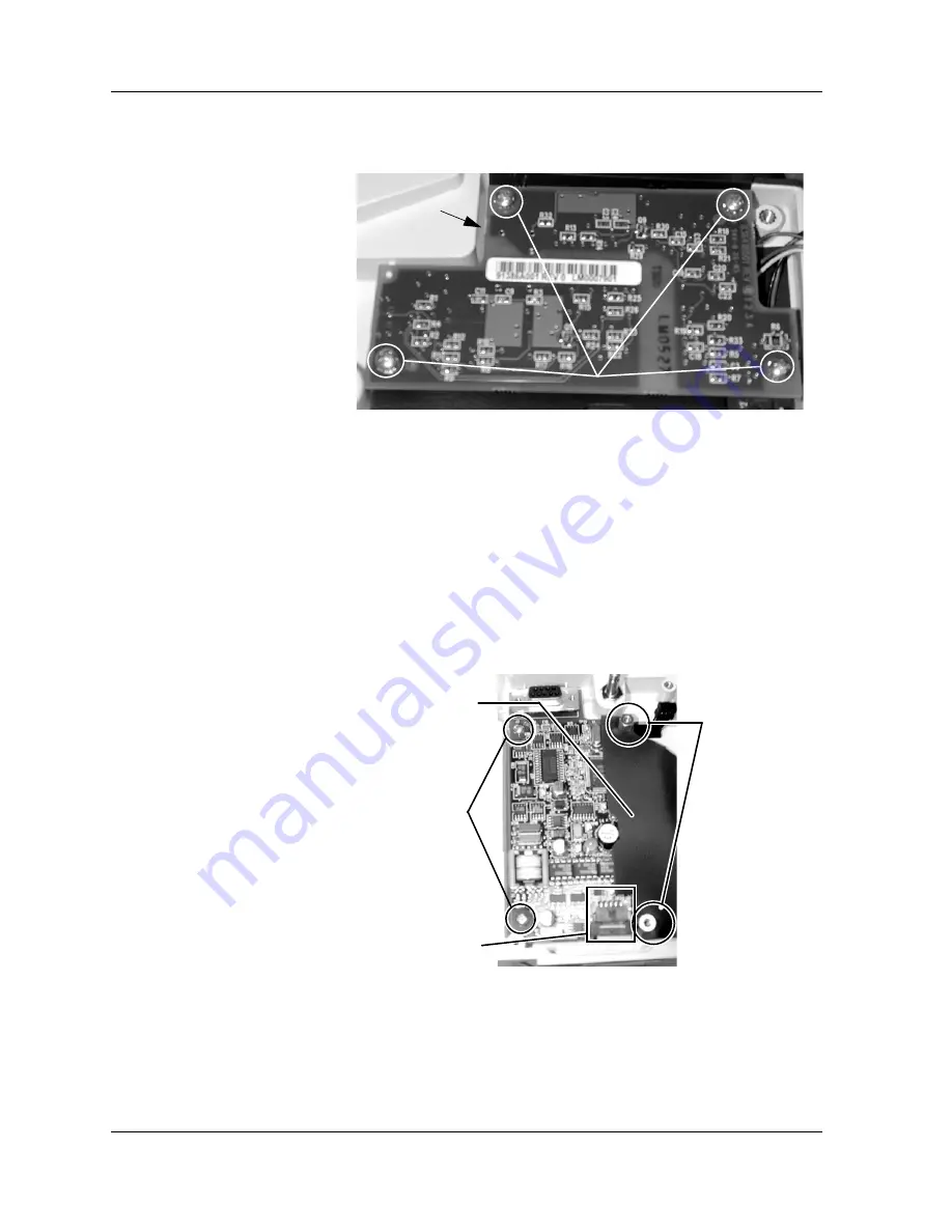
4. Remove the four (4) screws (pn 40995B005) from the FasTemp
Isolation PCB.
Figure 7-21: Remove Isolation Board Screws
5. Carefully lift up the Isolation PCB (pn 91386A001).
6. Remove the Temp cable (pn 90931A001) from the connector
beneath the PCB.
NOTE
: DO not tuck the temp cable into the opening. Add RN to
connector after reassembly.
NOTE
: The connector is locking. Inserting the cable incorrectly
will cause damage if powered up.
7. Remove the standoffs (pn 42476B001) that hold the DOX SpO
2
Board to the base assembly.
Figure 7-22: DOX SpO
2
PCB
NOTE
: Insulator is placed on top of PCB, then standoffs.
8. Remove the insulator.
9. Remove the two (2) screws (pn 40995B005) that are holding the
DOX SpO
2
PCB to the base assembly. Torque is 5 in. lbs.
Remove Screws (torqued @ 5 in lbs)
Temp cable
underneath PCB
Standoffs
Insulator
Screws
J1
Torque @
2 in lbs
Summary of Contents for 506DN3
Page 12: ......
Page 56: ......
Page 62: ......
Page 90: ......
Page 156: ......
Page 184: ......
Page 225: ......
Page 229: ......
Page 230: ......
Page 231: ......
Page 232: ......
Page 233: ......
Page 237: ......
Page 238: ......
Page 239: ......
Page 240: ......
Page 241: ......
Page 242: ......
Page 243: ......
Page 244: ......
Page 245: ......
Page 247: ......
Page 248: ......
Page 249: ......
Page 250: ......
Page 251: ...DO NOT SCALE PRINT DO NOT SCALE PRINT REV DATE DESCRIPTION BY...
Page 253: ......
Page 254: ......


