
J U N C T I O N B O X J B 4 4 X X - M A N U A L
20120608
FRABA VITECTOR GmbH
6 / 6
Carlswerkstr. 13 C · D - 51063 Köln
Tel.: +49 (0) 221 - 9 62 13-85, T49 (0) 221 - 9 62 13-60, www.vitector.eu
EN
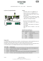
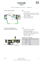
Usage of connection box JB 3512
Note:
•
Remove Shunt
Stx
•
Connect 5-lead Cable (CS 5021, CS 5022, CS 5023)
between
Stx
one of the two OSE-sensor connection
sockets, (e.g.
OSE-Tx
)
•
Bridge all unused Stop terminals
•
Utilise Connection-PCB AC 1320
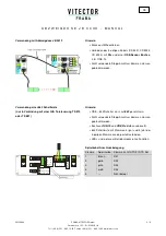
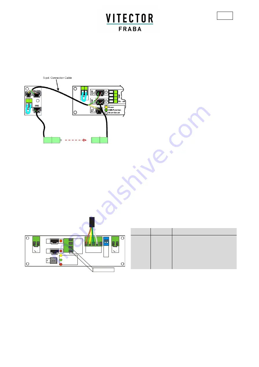
Connection of an 8k2 Resistive strip
(only for GfA control unit TS 970 or TS 981)
O
S
E
-T
x
O
S
E
-R
x
S
T
x
Power
OSE-Function
Short Circuit
Tx - wh 1
bn 2
gn 3
Rx - wh 4
O
S
E
ON
12
O
S
E
-
8
k2
4p
o
l -
5
po
l
1
-
b
n
2
-
y
e
3
-
g
n
4
-
w
h
1
-
g
y
Stop
Stop
8k2 Edge
Note:
•
OSE-8k2 switch has to be set to
8k2
•
Bridge all unused Stop terminals
•
Sockets
OSE-Tx
und
OSE-Rx
. remain unused
•
Connect 8k2 resistive strip to 4-pol terminal between
wh
and
gn
as indicated on the PCB
•
LEDs are out of function
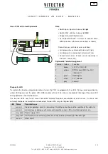
Spiralcable Terminal Assignment
Terminal Colour
Terminal on GfA TS 970/TS 981
1
brown
X2.1
2
yellow
X2.2
3
green
X2.3
4
white
X2.4
5
---
unused


