EN
9
UNIT STARTING AND
WORKING
WARNING; Never take the
electronic board out of the control
box.
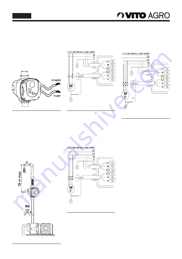
The wiring diagram inside the
terminal block will show you how
to make correct connection. Wrong
connection will destroy
the whole electronic circuit.
Fig. 1
Cable used for connection must be
a three wired one with compulsory
grounding end.
The four screws on the panel board
and the two nuts for fixing cable
must be well fastened to avoid
water entering into the control box
and damaging the electronic circuit.
No taps can be installed between
the pump and the unit.
Fig. 2
Wiring diagrams for connecting
the unit to different kinds of pumps
motors.
Wiring diagram for connection of
single phase pumps up to 1.1 kW.
Fig. 3
Wiring diagram for connection of
single phase pumps over 1.1 kw
through remote control system.
Specification for remote control
system: minimum capacity of
contact - 4 kW or 5.5 hp.
Fig. 4
Connection diagram for three-phase
pumps through of remote control
system.
Specification for remote control
system: minimum capacity of
contact - 4 kW or 5.5 hp.
Fig. 5
INSTRUCTIONS OF
CORRECT INSTALLATION
If the column of water between the
pump and the highest tap exceeds
15 m, the unit cannot be installed
directly on the pump, but it has to
be raised until the column of water
between the unit and highest tap
does not exceed 15 m.
If column of water is 20 m, from the
pump, the unit must be placed 5 m
higher than the pump.
The unit is equipped with a check
valve to prevent the pipeline from
losing pressure.
The pump should be kept in a
vertical position.


