For direct (manual control) mode, press enter, as the direct mode is highlighted when the menu pops-up. The next prompt is as
follows:
ENTER MAX VOLTAGE
1000
VOLTS
This prompt allows the operator to set a maximum test voltage. This limit prevents the user from inadvertently exceeding the
intended range of output voltage. The 1000 VDC shown is the default limit. To enter another limit, simply press the number keys
for the desired value. The range of test voltages for the Megaohm function is from a low of 100 VDC to a maximum of 2500
VDC. Once the desired voltage limit has been entered, press enter to advance to the next step.
ENTER MIN RESISTANCE
1.000
MEGOHMS
The minimum resistance value is a built-in safety feature. Should the load resistance drop below this value the 944i will
automatically stop the test. The default value is 1 megaohm. The lowest allowable minimum resistance value is 100 K
Ω
. Should
the user care to use a different value, just enter the new value and press the enter key. To change the units from M (mega) to G
(giga) or K (kilo) use the up down cursor arrows.
As in AC and DC, the Megaohm function of the 944i requires a two-step key press sequence
that the device under test is properly
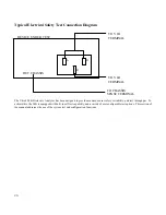
connected to the 944i test terminals. Please refer to the "Test Connections" section of the operating manual before proceeding.
WARNING!, failure to observe safety precautions may result in severe injury or death to the operator. Before beginning this
sequence, it is important to ensure that the device under test is properly connected to the 944i test terminals.
The display will prompt the user to press the HV enable key as follows:
HIGH VOLTAGE ENABLE
REQUIRED
Once the test connections have been verified, press the HV enable key. After pressing the high voltage enable key the final prompt
is:
PRESS ENTER TO
START
TEST
Upon pressing the enter key the 944i will sound a number of warning beeps while flashing the HV enable indicator. If the auto-
ground test feature is enabled, the unit will automatically check the chassis of the DUT for earth ground continuity before
applying high voltage to the DUT.
The starting test voltage for high resistance measurement is 100 VDC. The test display is arranged with the top row indicating the
output voltage in both digital read-out and bar graph formats. The multi-segment bar graph represents the proportion of output
voltage relative to the preset voltage limit. For example, if the output setting was 500 volts and the preset voltage limit was 1000
volts approximately 50% of the bar graph segments will be illuminated.
Adjacent to the bar graph is a digital display of the output voltage setting. The display is a four digit display with a resolution of
one volt. The digit that is blinking is the digit that is presently subject to modification by the up/down cursors. To increase the
output voltage, press the up arrow. To decrease the output voltage, press the down arrow. To move the blinking digit to the left or
right use the left/right cursor controls.
When the user has completed direct mode testing, press the High Voltage Disable/Stop key to remove the high voltage output.
ALWAYS
verify that the high voltage present indicator has extinguished prior to handling the test leads.
.........................................................................................
Low Resistance (Continuity) Function
The Vitrek 944i Dielectric Analyzer is a true multi-function tester. In addition to high voltage testing, the 944i has built-in low
resistance measurement capability. The 944i can measure resistance from 0.001 ohm to 8.5 ohms, with the option LO-500 this
range can be extended up to 500 ohms. The measurement is made with a 50mA test current. For regulatory compliance testing of


