background image


48

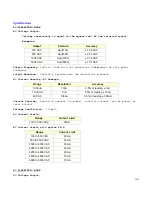
Specifications


AC DIELECTRIC MODE


AC Voltage Output: 


Voltage uncertainty is equal to the square root of the selected output. 

 Examples: 

Output   


Formula  


Accuracy


100 VAC


Sqrt(100)


± 10.0 VAC


500 VAC


Sqrt(500)


± 22.4 VAC


1000 VAC


Sqrt(1000)


± 31.6 VAC


5000 VAC 

Sqrt(5000) 

± 70.7 VAC 

Output Frequency:

 50Hz to 100Hz with 1Hz resolution independent of line power 

frequency. 


Output Waveform:

  Digitally synthesized, low distortion sinewave. 


AC Current Sensing (AC Leakage

)

:


Range


Resolution


Accuracy


13.00uA


10nA


0.5% of reading ± 1uA


1.300mA


1uA


0.5% of reading ± 10uA


40.0mA


100uA


0.5% of reading ± 500uA


Current Sensing:  

Resistive current (in-phase), reactive current (out-of-phase) or 

total current. 


Voltage Coefficient:  

100pA/V    

AC Current Limits: 

Range


Current  Limit


100 to 5,000 VAC


35mA


AC Current Limits with option FR-4: 

Range


Current  Limit


100 to 500 VAC


20mA


500 to 3500 VAC


35mA


3500 to 4000 VAC 

30mA 

4000 to 4200 VAC 

25mA 

4200 to 4400 VAC 

20mA 

4400 to 4600 VAC 

15mA 

4600 to 5000 VAC 

10mA 


DC DIELECTRIC MODE


DC Voltage Output: 

Summary of Contents for 944i

Page 1: ...rek Corporation 9880A Via Pasar San Diego CA 92126 USA V 858 689 2755 F 858 689 2760 Copyright Vitrek Corporation 1992 2008 all rights reserved rev 2008 04 23 Table of Contents Advanced Test Equipment Rentals www atecorp com 800 404 ATEC 2832 Established 1981 ...

Page 2: ...ctric Strength Testing 13 AC Dielectric Strength Testing 15 Insulation Resistance Megaohm Measurement 17 Earth Continuity Low Ohms Measurement 18 Adding Test Steps 19 Storing Tests 19 Recalling Tests 20 Editing Tests 20 Printing Test Reports 21 Aborting Tests 21 4 Test Connections Test Connection Safety Precautions 23 Connecting to Earth Grounded Devices 23 Connecting to Non Grounded Devices 24 Ty...

Page 3: ...allel Printer Port 39 Vitrek Instrument Control Loop VICL 39 7 Options and Accessories Description of Optional Items 40 8 Maintenance Routine System Inspection and Maintenance 42 Verification Procedure 43 Performing an External Auto Calibration 45 EPROM Upgrade Procedure 48 9 Specifications 944i Performance Specifications 50 ...

Page 4: ...ent at 9880A Via Pasar San Diego CA 92126 phone 858 689 2755 fax 858 689 2760 Certification Vitrek Corporation certifies that this instrument was thoroughly tested and inspected and found to meet published specifications when shipped from the factory Vitrek Corporation further certifies that the calibration of this instrument is traceable to the National Institute of Standards and Technology to th...

Page 5: ...d DO NOT REMOVE COVERS Operating personnel must not attempt component replacement or internal adjustment Dangerous voltages may exist internally even when the power is switched off Because of the dangers of introducing additional hazards do not install substitute parts or perform any unauthorized modifications to the instrument Refer the unit to qualified maintenance personnel or to your nearest V...

Page 6: ...f the instrument fails to operate notify the carrier s agent and Vitrek or your local Vitrek Service Center Retain the shipping carton for the carrier s inspection Initial Adjustments The only adjustments required prior to operation of the 944i are selection of the local power source voltage and verification that the correct fuse for this voltage is fitted The supply voltages and fuses are listed ...

Page 7: ...High Voltage Present High Voltage Enabled Testing VICL Port Active Printing RS232 Active GPIB Remote Talk Listen and SRQ remote service request Mode Keys The two columns of keys to the right of the status indicators are the mode keys A listing of the 10 mode keys from left to right top row to bottom row is as follows Recall Test Program Edit Test Program Print Menu System Test System Configuration...

Page 8: ...o the 944i through a three prong internal type power receptacle A power cord which mates with this receptacle is also provided RS232 Port The 944i uses a 9 pin male D sub connector for serial communications when the option IF 4 interface package is ordered IEEE 488 Port Access to the optional IEEE 488 GPIB interface is accomplished through this connector VICL SIJ Ports The 944i is configured with ...

Page 9: ...ed 50 C while in operation or 70 C while not in operation Earth Ground Connection The power connector should be a three contact device meeting the safety requirements of the area in which the 944i is to be used and should only be mated with a three contact connector where the third contact provides ground connection If the power is provided through an extension cable then the ground connection mus...

Page 10: ... and is highlighted when the Direct Automatic menu pops up To select Direct mode simply press enter The following prompt will appear ENTER MAX VOLTAGE 1000 VOLTS This prompt allows the operator to set a maximum test voltage This limit prevents the user from inadvertently exceeding the intended range of output voltage The 1000 VDC shown is the default limit To enter another limit simply press the n...

Page 11: ...utput press the down arrow To move the blinking digit to the left or right use the left right cursors If at any time during direct output control the preset maximum current limit is exceeded the test is automatically aborted and a maximum current exceeded message will be displayed When the user has completed direct mode testing press the High Voltage Disable Stop key to remove the high voltage out...

Page 12: ...de has been selected the 944i will prompt the user to set a current limit with the following message ENTER MAX CURRENT 10 0 mA This value sets the maximum amount of leakage current which the 944i will source prior to shutting down the test Any current which exceeds this limit will cause the unit to automatically stop the test The default value is 10 0 mA However any value between 1nA and 35 mA may...

Page 13: ...HV enable key After pressing the high voltage enable key the final prompt is PRESS ENTER TO START TEST Upon pressing the enter key the 944i will sound a number of warning beeps while flashing the HV enable indicator If the auto ground test feature is enabled the unit will automatically check the chassis of the DUT for earth ground continuity before applying high voltage to the DUT The starting tes...

Page 14: ...roing of test lead resistance is essential to obtaining reliable results To facilitate the canceling of lead wire resistance the 944i will provide a brief message as follows PRESS 0 TO NULL LEAD RESISTANCE It is recommended that the user null the lead set periodically to obtain the most accurate results Always do a null when a new or different set of test leads are used with the unit If you wish t...

Page 15: ...C Dielectric test press the VDC key located under the display window Upon pressing the VDC button the following display prompt will appear DC DIELECTRIC TEST DIRECT AUTOMATIC This message confirms that the DC function has been selected and offers both operating modes Use the right cursor arrow to highlight the Automatic mode and then press enter The following prompt will appear ENTER TEST VOLTAGE ...

Page 16: ... interested in repeating the test just entered it is recommended that the test be stored To run the test that has just been set up press enter while the run is highlighted As in direct mode testing the automatic mode of the 944i requires a two step key press sequence prior to initiating high voltage testing Before beginning this sequence it is important to ensure that the device under test is prop...

Page 17: ...ow amplitude signals To prevent erroneous phase measurement the 994i will default to total current sense when phase signals are below the minimum threshold Once the current sense mode has been selected the 944i will prompt the user to set a current limit with the following message ENTER MAX CURRENT 10 0 mA This value sets the maximum amount of leakage current which the 944i will source without fai...

Page 18: ...is interested in repeating the test just entered it is recommended that the test be stored To run the test that has just been set up press enter while run is highlighted As in direct mode testing the automatic mode of the 944i requires a two step key press sequence prior to initiating high voltage testing Before beginning this sequence it is important to insure that the device under test is proper...

Page 19: ...st developer to automatically set the ramp rate so that the output voltage linearly increases up to the test voltage The slew rate can be set from 1 volt per second to 2000 volts per second If 100 v s is the desired ramp rate then press enter If another rate is desire use the number keys to input a new value and then press enter The next prompt is as follows ENTER MIN RESISTANCE 1 000 MEGOHMS The ...

Page 20: ...e the dwell time begins the timer will reset and count down to the end of the test Low Resistance Continuity Function In addition to high voltage testing the 944i has built in low resistance measurement capability The 944i can measure resistance form one milliohm to 8 5 ohms The 944i uses a 50mA test current in the low ohm mode For regulatory compliance testing of earth ground continuity at high c...

Page 21: ...ohms test has been chained to a high voltage test If the 930i option is selected then the standard prompts of the 930i will follow and the 944i will download the test to the 930i when the test is run Adding Test Steps The 944i is capable of storing up to 99 test programs with a maximum of 200 test steps The maximum number of steps in any one test is 50 When operating the 944i in the automatic mode...

Page 22: ...Test Programs NOTE All current firmware versions have been found to develop corrupted RAM if a test is edited For best assured performance delete the test you wish to change and re enter it from scratch using the instructions below It is recommended that you do not use the INSERT or CHANGE functions in the EDIT menu It is helpful to have a printout of the test database when editing a test program ...

Page 23: ...el port and press enter ENTER DUT S N _ _ _ _ _ _ _ _ _ _ _ Numeric entry can be done using the number keys Alpha characters may be entered using the up down cursor arrows Once the DUT serial number has been entered press the enter key and the printout will commence To repeat the test on the existing or new device under test select the retest option and press enter To exit the test mode select the...

Page 24: ...esults whenever multiple choices are offered in a menu selection each choice has a corresponding number The items are numbered from left to right For example if the retest option shown in the above menu is desired a single press of the number 3 would start a new test The number 2 would initiate the printout routine ...

Page 25: ... 944i and its chassis sense terminal It is recommended that a low resistance test be conducted on earth ground devices to verify ground continuity prior to dielectric testing Connecting to Devices with Earth Grounds Earth grounded devices must be isolated from earth ground when conducting dielectric strength tests with the 944i This will insure that all leakage current flows through the 944i and i...

Page 26: ...ature of the 944i Otherwise the unit will fail the pretest auto ground check and no further testing will commence An alternate method is to provide a low impedance connection between the V LO terminal and the Chassis Sense terminal CAUTION Care must be taken to remove this connection after testing so that the chassis sense is not defeated when testing earth grounded chassis devices ...

Page 27: ...igh voltage is present on this terminal 2 V Lo Terminal The V LO terminal is the reference terminal for leakage current measurements and is also one of the two terminals used in making a continuity low resistance measurement This terminal typically connects to the earth ground pin of the DUT Inside the TL 115 and the TL IEC this terminal is connected to the earth socket of the test adapter 3 Chass...

Page 28: ...I TERMINAL The Vitrek 944i Dielectric Analyzer has been designed to provide maximum user safety reliability and test throughput To achieve this the 944i is equipped with built in self test capability and a variety of user configurable test options This section of the manual addresses the use of the system test and configuration functions ...

Page 29: ...efault cal data The unit should be referred to qualified maintenance personnel for calibration and inspection of the CMOS RAM battery which has a five year rating SELF TEST CLOCK OK The next two messages are provided in the self test as a configuration status indication For details on the other configuration options consult the system configuration instructions in this section of the manual SELF T...

Page 30: ...atically advance 12 hours When all adjustments have been made press enter to complete the clock setting procedure Safety Control Settings To adjust safety settings select the safety option from the main CNFG menu The display will then prompt with the following items which may be adjusted Beep Arc SS safety lead sensing Lo ohm automatic ground testing Controlling the HV Warning Beeper To set the nu...

Page 31: ...hen select ON or OFF Ramp Current Limit For applications where the initial charge current is relatively high and the final leakage current is considerably smaller the Vitrek 944i offers the ability to set different maximum current limits during the ramp up and dwell periods Additionally the higher ramp current limit will apply for the specified hold period upon reaching the test voltage before the...

Page 32: ...es and prompts the operator to interrupt the short circuit condition allowing the operator to select a new DUT test point if desired the 944i will automatically begin the next step of the test upon circuit closure Front Panel Lockout The LOCK option allows one to lockout all front panel keys with the exception of the Recall key When in the locked mode operators can recall and execute tests stored ...

Page 33: ...f the GPIB Command Syntax The GPIB command set is provided on the following pages A description of each command a listing of its associated arguments and a sample basic program listing are provided where appropriate All voltage values are expressed as integers current and resistance values may be expressed in scientific notation format NOTE Previous versions of the manual indicate that a 2000 V S ...

Page 34: ...rguments VDC Selects DC Volts function test voltage 100 5000 V Integer format slew rate 1 1999 V S Integer format max current 1 nA 35 mA Scientific notation format min current 0 35 mA Scientific notation format max ramp current 1 nA 35 mA Decimal format Only necessary when in RAMP_I mode test time 5 999 S 0 sets test time to indefinite ramp current hold time Must be test time Use 0 seconds if ramp...

Page 35: ...o the 944i waits 30 for test completion and then returns the result 40 to the bus controller 50 DIM Result 120 60 ASSIGN V944 TO 1410 70 REMOTE V944 80 ABORT 14 90 CLEAR 14 100 Issue test and command to run 110 OUTPUT V944 ADD MEG_OHM 1000 100 1 0e 6 5 RUN 120 Poll until test is complete 130 Stb SPOLL V944 140 IF Stb 8 THEN 130 150 PRINT Stb Stb 160 Get test results 170 OUTPUT V944 RSLT 180 ENTER ...

Page 36: ...waits 30 for test completion and then returns the results 50 DIM Result 120 60 ASSIGN V944 TO 1410 70 REMOTE V944 80 ABORT 14 90 CLEAR 14 100 Issue test and command to run 110 OUTPUT V944 ADD LO_OHM 2 0 5 RUN For 944i 110 OUTPUT V944 ADD LO_OHM 25 60 1 0E 1 0 5 RUN For 930i 120 Poll until test is complete 130 Stb SPOLL V944 140 IF Stb 8 THEN 130 150 PRINT Stb Stb 160 Get test results 170 OUTPUT V9...

Page 37: ...o 5 max chassis resistance in ohms ramp down 0 sets down slew rate to max 1 sets ramp down rate to same as ramp up saf sns 0 off 4 on for all dielectric tests IR mil 0 off normal MΩ 1 quick pass IR mode Example 10 File T3 IBW 20 This sends a CNFG command to the 944i 60 ASSIGN V944 TO 1410 70 REMOTE V944 80 ABORT 14 90 CLEAR 14 110 OUTPUT V944 CNFG 0 2 1 0 4 0 220 STOP 230 END ETRIG Argument none F...

Page 38: ...l status with fault type if any Fills output register with an ASCII representation of a decimal value indicating one of the following test results Register data remains available until cleared with a CLS RST or a new test is run 0 TEST PASSED Fault Codes 1 MAX RESISTANCE EXCEEDED 2 MIN RESISTANCE EXCEEDED 3 OVERANGE 4 COMPL VOLTAGE EXCEEDED 5 AC SYSTEM FAULT 6 HIGH RESISTANCE 7 USER ABORTED 8 ARC ...

Page 39: ...he 944i will terminate all commands with a line feed character n via the GPIB interface NOTE There is currently no read terminator added to responses via the serial port RUN Arguments none Function Runs current test Example RUN This command starts execution of the current test CLS Arguments none Function Resets 944 GPIB status registers Example CLS This command clears all status registers IDN Argu...

Page 40: ...to a PC serial port using a straight through 9 pin male to 9 pin female extension type cable Sending Commands Data may be exchanged with the 944i serial port using the following protocol Baud Rate 9600 Stop Bits 1 Parity none Handshaking no Word width 8 Echo Mode echo off Command Set for RS232 The command set available for serial operations is the same as that for GPIB Except for the different rea...

Page 41: ... function from the time date screen press the MENU key in the OPTIONS row The following menu appears PRINTER SETUP CR LF CR LF With most printers selecting CR carriage return or LF line feed will result in a single spaced printout Selecting CR LF will send both a carriage return and a line feed at the end of each line and may result in double spaced printouts VICL Vitrek Instrument Control Loop Th...

Page 42: ...aving to handle the lead while the test voltage is applied RM 1 Rack Mount Kit The RM 1 permits the 944i to be used in a standard 19 rack Instructions for installing the RM 1 are provided in the Getting Started section of this manual GP 1 GP 2 GPIB Cables The GP 1 and GP 2 are 1 and 2 meter length IEEE 488 GPIB cables SIJ 1 Safety Interlock Jack Option provides a 2 5mm jack in the rear of the unit...

Page 43: ... option installed differ from a standard unit RPO Rear Panel Outputs Provides V Hi V Lo and Chassis Sense outputs at the rear of the unit FS 1 Four Wire Fail Safe option Provides four wire Lo Ohms measurement capability V Lo and Chassis sense outputs are BNC connectors and limits the current output in Lo Ohms mode to 8 5mA PLC 2A Programmable Logic Controller interface Option provides a 5 pin DIN ...

Page 44: ...more often If the filter is allowed to become restricted overheating can occur causing damage to the electronic components Should the filter require cleaning the finger guard snaps off to provide easy access to the filter element A thorough rinsing in a warm soap water solution should remove any build up Insert the filter element back into the finger guard and snap into place Note that the finger ...

Page 45: ...roper Calibration Sheet at the end of this section Once completed with the VDC tests select the VAC direct mode and run the tests specified on the Calibration Sheet at the end of this section 1 2 Current Measurement Accuracy First connect the V HI terminal to a Vitrek 4610A Precision High Voltage Resistance Standard or equivalent and the V LO terminal to the Common terminal Select the VDC direct m...

Page 46: ... 1 MΩ 1 mA AC mA AC 1 000 mA AC 1 000 35 µA AC Hi pot Leakage 1000 VAC 100 kΩ 10 mA AC mA AC 10 mA AC 10 550 µA AC Lo Ω Variable 1Ω 1 000 Ω Ω 1 Ω 1 33 mΩ Lo Ω Variable 5Ω 4 999 Ω Ω 4 999 Ω 4 999 45 mΩ Measurement Test Test Nominal Incoming Outgoing Type Voltage Load Values Readings Dev Readings Dev Max Tol Hi pot Voltage 100 VDC 100 MΩ 100 VDC VDC 100 VDC 100 15 0 VDC Hi pot Voltage 500 VDC 100 MΩ...

Page 47: ...EQUIRED Press the HV Enable push button Three warning beeps will sound and the high voltage warning LED s will flash CAUTION after this point high voltage will be present on the output of the 944 The display will respond with ADJUST 500 VOLTS After a few seconds the display will respond with a screen displaying two meters the top one will be displaying the voltage that the 944i is putting out You ...

Page 48: ...tion routine the display will show the following message REMOVE CONNECTIONS THEN PRESS ENTER Remove all connections from the 944i except the short from V LO to Chassis Sense If no adjustment of the current measurement is needed the current calibration portion of this procedure may be skipped by pressing CLR at this prompt To continue press enter The display should respond with APPLY 1 8µA FROM VLO...

Page 49: ...f power during the routine When enter is pressed the display will respond with STORING CALIBRATION CONSTANTS FOLLOWED BY CALIBRATION COMPLETE THANK YOU FOLLOWED BY ENTER Press enter when ready and the calibration screen will show up again CALIBRATION VOLTS CURRENT EXIT You may exit by selecting EXIT or pressing 3 on the keypad Once the calibration n procedure is complete another verification proce...

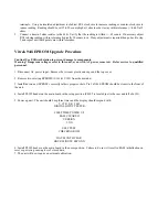
Page 50: ... removed Refer service to qualified personnel 1 Disconnect AC power input Remove the two rear plastic end caps and the top cover 2 Remove two existing EPROMS U101 U102 from the main bd 3 Install the two new EPROM s correctly in their proper sockets Pin 1 of the EPROM should be closest to the front of the unit 4 Install PL102 header on the main board in the setup position PL102 is located just to t...

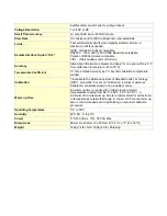
Page 51: ...w distortion sinewave AC Current Sensing AC Leakage Range Resolution Accuracy 13 00uA 10nA 0 5 of reading 1uA 1 300mA 1uA 0 5 of reading 10uA 40 0mA 100uA 0 5 of reading 500uA Current Sensing Resistive current in phase reactive current out of phase or total current Voltage Coefficient 100pA V AC Current Limits Range Current Limit 100 to 5 000 VAC 35mA AC Current Limits with option FR 4 Range Curre...

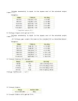
Page 52: ... 5 AC Voltage specs remain the same as the standard 944 as described above Examples Output Formula Accuracy 100 VDC Sqrt 100 1 5 15 0 VDC 500 VDC Sqrt 500 1 5 33 5 VDC 1 000 VDC Sqrt 1000 1 5 47 4 VDC 5 000 VDC Sqrt 5000 1 5 106 1 VDC 7 000 VDC Sqrt 7000 1 5 125 5 VDC 10 000 VDC Sqrt 10000 1 5 150 0 VDC DC Current Sensing DC Leakage Range Resolution Accuracy 1 800uA 1nA 0 4 of reading 6nA 18 00uA ...

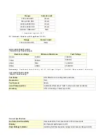
Page 53: ... 000VDC 65GΩ 2 5MΩ 2 500VDC Accuracy Combined uncertainty of DC Voltage Output Current Measurement Accuracy LOW RESISTANCE MODE Earth Continuity Full Scale 8 5Ω Maximum including lead resistance Resolution 1mΩ Test Current 50mA Lead Compensation Automatic offset circuit nulls out two wire lead resistance Accuracy 0 3 of reading 30mΩ up to 5Ω General Specifications Arc Detection Sensitivity User se...

Page 54: ...mperature Coefficient 0 1 times stated accuracy per C beyond calibration temperature window Calibration Traceable to the National Institute of Standards and Technology NIST Automatic Covers on calibration internal or external Calibration constants stored in non volatile memory Warm up Time No warm up time is required for units stored in ambient temperatures ranging from 64 F to 82 F 18 C to 28 C A...

Reviews: