95x Series Operating Manual - May 17, 2022
Page
103
of
155
SECTION 8
–
DIO INTERFACE
Using the 95x Digital Input & Output (DIO) interface the user may perform any combination of the following
–
•
Control the 95x using a PLC type device, starting, stopping, selecting a sequence, and determining the
pass/fail status
•
Control the 95x using external start and/or stop switches
•
Abort a test sequence when a safety interlock is opened
•
Allow the 95x to illuminate external safety indicators
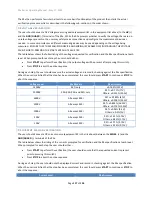
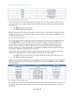
CONNECTOR AND PINOUT
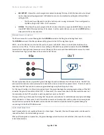
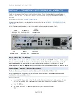
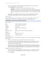
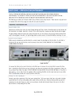
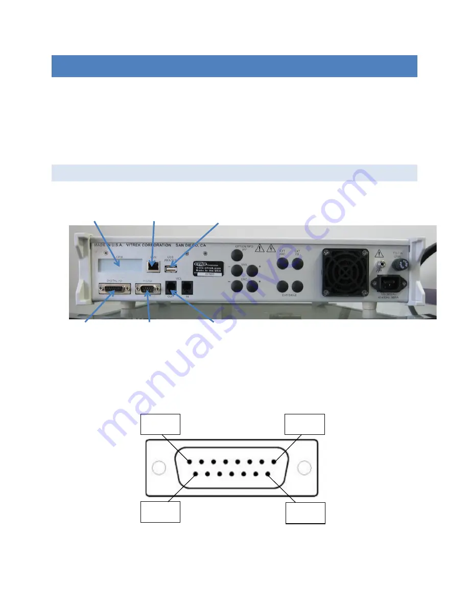
The DIO signals are available at the rear panel of the 95x in the 15-
pin connector identified as “DIGITAL I/O”
as
shown the photograph above. The 95x connector is a standard two-row 15-pin female Dsub connector; any
suitable male mating connector may be used.
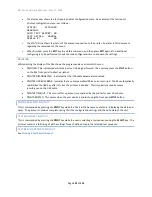
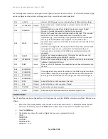
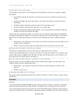
The diagram below shows the pin locations within the connector as viewed from the rear panel of the 95x.
GPIB
CONNECTOR
ETHERNET
CONNECTOR
USB
PRINTER
CONNECTOR
DIO
CONNECTOR
RS232
CONNECTOR
VICL
-
OUT
CONNECTOR
Pin 1
Pin 8
Pin 9
Pin 15

