95x Series Operating Manual - May 17, 2022
Page
113
of
155
PROCEDURE
Follow the prompts in the display of the 95x for the actual procedure as it varies between models and option
content.
•
Press
EXT
.
•
Press the UP-arrow
key to display “ADJUST CAL” on the lower display line,
and then press
ENTER
. The 95x
now prompts the user for entry of the calibration password.
o
If the user has not locked the calibration previously then there is no password in the 95x, so the
user may just press
ENTER
again to continue.
o
Otherwise, the user must enter the previously defined numeric password (using the numeric
keys on the front panel) prior to pressing
ENTER
.
o
If the calibration has previously been locked by a password, but it is no longer known to the user,
then please contact Vitrek for details regarding how to proceed.
•
The user is now prompted to enter a new calibration lock password.
o
If no change is required, then press
ENTER
(all zero digits is the selection for no password
protection of calibration).
o
If no password protection for calibration is desired but a password was previously defined, the
user should overwrite the password with all zero digits and then press
ENTER
.
o
If the password is to be changed, then enter the new password using the numeric keys on the
front panel and then press
ENTER
.
•
The user is now prompted to remove all leads. Ensure there are no connections to the front panel and (if
any) rear panel terminals then press
START
.
•
The 95x now performs a series of internal adjustments which require no user equipment or intervention.
•
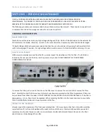
When the internal adjustments have completed, the display prompts the user to provide a short between
the
SENSE+
and
SENSE-
terminals. This is equipment #1 listed above. NOTE
–
this short circuit must have
less than 5uV of thermally induced voltage, the user may need to wait for some time after making
connections. Ensure that the short circuit is properly inserted into the terminals and then press
START
to
continue the procedure.
•
The 95x now automatically performs both a voltage zero and a 2-wire resistance zero adjustment. When
the 95x has completed its 2-wire zero adjustments, the user is prompted to provide a 4-wire zero. This is
equipment #2 listed above. NOTE
–
this short circuit must have less than 5uV of thermally induced
voltage, the user may need to wait for some time after making connections. Ensure that the short circuit
is properly inserted into the terminals and then press
START
to continue the procedure.
•
The 95x now automatically performs a 4-wire resistance zero adjustment. When the 95x has completed
its 4-wire zero adjustments, the user is prompted to remove the 4-wire short circuit. When it has been
removed press
START
to continue the procedure.
•
The user is now prompted to provide a source of 1000Vdc (equipment #3 listed above) between the
HV
(+) and
GND/GUARD
(-) terminals of the 95x. Apply the connections to the 95x terminals ensuring the
connections are to the correct terminals and with the correct polarity, and then set the source to provide
the voltage. DO NOT TOUCH TERMINALS OR CONNECTORS WHILE VOLTAGE IS APPLIED. When the
voltage is correctly applied press
START
to continue the procedure. The user is now shown the difference
in calibration at 1000Vdc between this calibration and the last calibration of the 95x. If the change is
acceptable then press
START
to accept it and continue the procedure, otherwise abort the calibration by
pressing
STOP
. NOTE
–
the 95x specification at this level is ±0.3%. The 95x display will show FAILED if the
calibration is out of range for calibration, not if the change is beyond the specification.

