95x Series Operating Manual - May 17, 2022
Page
61
of
155
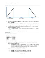
leftmost (time) setting to OFF. The 95x can be configured to not fail a test step when arcing is detected by
setting the ARC setting in the CNFG
–
TEST sub-menu to DETECT ONLY.
•
DISCHARGE
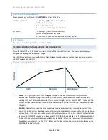
. Not available for the DCez type. Allows the user to program whether the discharge period
should use the same timing as the ramp period (AS RAMP), be as fast as possible (FAST) or skipped
(NONE). If NONE is selected but the next step is not of a DCez, DCW, or DCIR type then the FAST selection
is used when the sequence is run.
o
If a load has significant resistance in series with capacitance, then ensure that the discharging
current is within the capability of the series resistance to avoid it being damaged. If necessary,
reduce the maximum discharging current by reducing the CNFG
–
TEST
–
MAX DISCHARGE
setting.
•
ON FAIL
. Allows the user to program the 95x to abort the entire sequence (ABORT SEQ) or only this step
(CONT SEQ) if this step fails any of its checks. A safety related failure or a user abort (
STOP
button) always
aborts the entire sequence.
PERFORMING A MULTI-STAGE RAMP OR MULTIPLE VOLTAGE TESTS
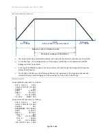
The 95x allows the user to skip the discharge phase if desired in DCW and DCIR types. If a step has DISCHARGE set
to NONE and the next step is also a DC Voltage Withstand type and is at a higher voltage than the preceding step,
then the discharge phase is skipped automatically. This enables the user to perform a multi-stage ramp with
optional dwell phases between each ramp stage.
If each step in such a series has non-zero dwell times then their leakage currents tests are performed normally,
however if the dwell time is set to zero in any but the final step then the dwell phase is also skipped in those steps
and any dwell leakage current (or resistance) limits defined in such a step will be ignored and the ramp phase of
the next step is immediately started after the end of the preceding stage ramp.
There are several scenarios where this capability assists the user, for example
–
•
If it is desired to perform leakage measurements at several voltages but it is not desirable to discharge
to zero between each voltage. The user can configure several steps, each with DISCHARGE set to
NONE. In this case there is no discharge phase between each step, only for the final step or if a failure
occurs.
•
If it is desired to perform leakage current tests at timed intervals, e.g., at 10-minute intervals, then the
user may configure many steps, all set for the same voltage and leakage current limits and with
DISCHARGE set to NONE. The first step would be configured with the desired ramp settings, all
remaining steps are configured with the desired interval between leakage checks as the ramp time.
All steps should have a short (but not zero) dwell time configured during which the leakage current
will be measured and checked against the limits. Up to 255 such steps can be configured in this
manner in a sequence.
•
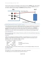
If ramping to a final voltage near the maximum ability of the 95x but the maximum current of the 95x
at the final voltage is limiting the ability to charge the load in a timely manner, then the user should
consider using a multi-stage ramp by using two (or more) steps. The first step should be configured
with a final voltage less than the desired final voltage and with a faster ramp rate and a higher
breakdown setting than would have otherwise been possible in a single step because of the lower final
voltage. This first step should be configured with DISCHARGE set to NONE and a 0sec dwell period.
The second step will be configured as required in all regards, having the slower ramp rate associated
with the lower possible breakdown current setting.

