95x Series Operating Manual - May 17, 2022
Page
73
of
155
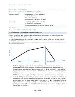
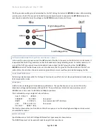
The 95x reports the actual highest voltage applied across the DUT following the end of this type of test step. Using
the reported actual voltage, the user can manually adjust the programmed test voltage level to accommodate
loading effects for future runs. Alternatively, the user can run a Lead Compensation with an example DUT
connected normally, in which case the 95x will save the measured highest voltage and automatically adjust the
output level in subsequent runs. Both of these methods assume that the load resistance does not vary significantly
with voltage; if the resistance does vary significantly then the user may need to manually adjust the test voltage
accordingly.
EXAMPLES
A nominally 10Kohm NTC thermistor is to be tested for breakdown at 400Vpk. The thermistor will only withstand
400V for a maximum of 100msec and will exhibit self-heating very quickly.
This is accomplished in a single step as follows
–
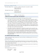
Seq 1 Step 1 PULSE
LEVEL: 400.0V
As required
POLARITY: U
As required
BREAKDOWN: 100.0mApk
Must be greater than the peak load current
RAMP: 1.0msec
Performed as fast as possible, the load has little capacitance
HOLD: 1.5msec
Performed as fast as possible, the load has little capacitance
ARC DETECT:4us 10mA
Optional
ON FAIL: ABORT SEQ
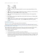
The actual test voltage may not have achieved the required test voltage with sufficient accuracy. When reviewing
the results the actual test voltage is displayed, as an example this may be 366V. The user may adjust the
programmed test voltage from the original 400V setting, to 400*(400/366) = 437V. Then the next time the step is
run the applied test voltage into this load will be closer to 400V. Alternatively, the user could run the test
sequence using the Lead Compensation feature with a nominal load connected; the 95x will then automatically
apply this in future runs of the test.
SPECIFICATIONS
Specifications are valid at the 95x terminals for 1 year at ambient temperatures within ±5C of calibration
temperature (add 5% of accuracy specification per C outside of this). All specifications are relative to the
calibration standards used. Add ½ digit to all accuracies for displayed results (results available with enhanced
resolution from interfaces).
TEST VOLTAGE AND LOADING CAPABILITY
Test Voltage
951-4i (standard build): 50V to 8000V
951-4i (opt. AC2): 20V to 2750V
Output Impedance
951-4i (standard build): 0.5H nominal output impedance
951-4i (opt. AC2): 1.4Kohm + 0.2H nominal output impedance
Max Load Current
Limited by the lesser of -
a) the test voltage and output impedance
b) 145mA (288mA for Opt. AC-2).
MEASURED TEST VOLTAGE ACCURACY
Test Voltage Accuracy
<(± 0.5% ± 5V ± (0.2V per mA load))


