95x Series Operating Manual - May 17, 2022
Page
83
of
155
•
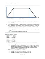
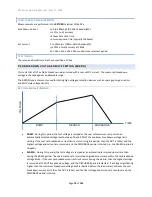
RAMP
. Only available for the GB type. Allows the ramp time period to be programmed either as a time
or rate. The
UNIT
key toggles the selection between these two methods. In the majority of cases a zero
setting should be used.
•
DWELL
. Allows the dwell time period to be programmed or set to be user terminated (with the
START
button) by pressing the
LIMIT
key while this setting is selected.
•
Test
. Only available for the GB type (the GBez type is always set to test the RMS impedance). Allows the
user to define the impedance measurements to be checked against range limits. The available selections
are
–
o
RMS.
Selects that the impedance check is performed on the RMS impedance measurement.
o
INPHS.
Selects that the impedance check is performed on the in-phase (i.e., resistance)
impedance measurement.
o
QUAD.
Selects that the impedance check is performed on the quadrature (i.e., reactance)
impedance measurement.
•
Lim
. Allows the user to define ranges within which the selected impedance measurement is considered a
PASS during the dwell period. The range can be entered in units of impedance or voltage, the
UNIT
key
toggles the selection. The user may optionally disable the lower limit by entering a zero value for it.
o
In-Phase and Quadrature measurements can be of either polarity; the limits are applied to the
measurement without regard to polarity.
•
DISCHARGE
. Only available for the GB type. Allows the user to program whether the discharge period
should use the same timing as the ramp period (AS RAMP), be as fast as possible (FAST) or skipped
(NONE). If NONE is selected but the next step is not of a GB type, then the FAST selection is used when
the sequence is run. In the majority of cases, FAST should be used.
•
ON FAIL
. Allows the user to program the 95x to abort the entire sequence (ABORT SEQ) or only this step
(CONT SEQ) if this step fails any of its checks. A safety related failure or a user abort (
STOP
button) always
aborts the entire sequence.
CONNECTING TO THE DUT
for general wiring and safety recommendations.
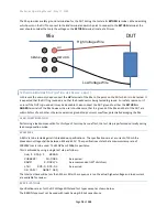
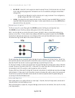
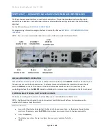
The 95x requires that the DUT (at least that portion which is being measured) is floating with respect to ground.
When making 4-terminal measurements the resistance of the wires, the contact resistance to the DUT, and the
contact resistance within the 95x front panel terminals are not included in the result, the only recommendation is
that the
and
SOURCE-
wires be of sufficient gage to withstand the user set test current.
When wired as shown below, the actual resistance measured is that between the innermost connection points to
the DUT (i.e., between the
SENSE+
and
SENSE-
connections).


