95x Series Operating Manual - May 17, 2022
Page
92
of
155
TEST TIMING
Test
0.02 to 9999sec or user terminated
<(± 0.05% ± 100ms) accuracy
Delay
0.00 to 9999sec
<(± 0.05% ± 100ms) accuracy
SWITCH UNIT CONTROL (SWITCH)
This type is used to control one or more external Switch Matrix Units (either Vitrek 948 or 964 units).
NOTE
–
to be able to define or edit a SWITCH test step the 95x must already be configured to control one or more
switch matrix units, see
Controlling External Switch Matrix Units
ACTIONS WHILE RUNNING
The external switch matrix units are controlled by the 95x in three periods as follows
–
1.
Pre-switch Period
. During this period, the 95x checks for the presence of each configured switch matrix
unit and also delays for at least the user set pre-switch delay period. If a configured switch matrix unit
fails to be detected, then the sequence is aborted. As soon as all units have been detected and the
minimum delay has expired, the switch command period is started.
2.
Switch Command Period
. During this period all configured switch matrix units have their relays
commanded into the user set states. As soon as this is completed the post-switch period is started.
3.
Post-switch Period
. The 95x stays in this period until the user set post-switch delay has expired. This
period allows for relay and wiring settling after changing the relay states. As soon as the delay has
expired the next test step in the test sequence is started.
CONFIGURING
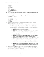
An example SWITCH type menu is as follows
–
Seq 1 Step 1 SWITCH
PRE-DELAY: 0.00sec
POST-DELAY: 0.25sec
#1: 0000000000000000
•
PRE-DELAY
. Allows the pre-switch delay to be specified.
•
POST-DELAY
. Allows the post-switch delay to be specified. When controlling a Vitrek 948 this should be
set to a minimum of 0.20sec, for a Vitrek 964 this can be set to zero if there are negligible wiring settling
requirements.
•
#1
. Allows the user to specify, using a hexadecimal code, the required relay states for switch matrix unit
#1. If configured for more than one switch matrix unit, there are further menu lines added for each
additional switch matrix unit. If configured for a Vitrek 948 then this menu line has 14 characters, for a
Vitrek 964 it has 16 characters. The hexadecimal code sets a binary code defining the required states of
relays #64 through 1 (for a 964) or #56 through 1 (for a 948) in left-to-
right order. A ‘1’ in this code
indicates that the relay is to be in the ON state. See the relevant switch matrix manual for further details
regarding setting these codes. The user should ensure that the state of any relay which is not actually
fitted in the switch matri
x unit is ‘0’.

