95x Series Operating Manual - May 17, 2022
Page
104
of
155
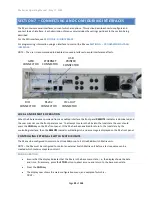
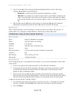
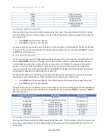
The following table contains a description of the signal on each pin in the connector. Each input and output signal
can be configured as the active level being low or high, or each input may be disabled.
CONFIGURING
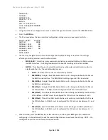
The DIO interface may be configured from the front panel by using the DIGITAL I/O sub-menu of the CNFG menu as
follows
–
•
Ensure that the display indicates that the 95x is in the base menu state, i.e., the display shows the date
and time. If necessary, press the
STOP
button to abort a menu and return to the base menu state.
•
Press the
CNFG
key.
•
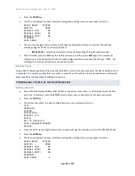
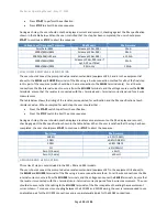
The display now shows the main configuration menu, an example of which is
–
TEST…
PRINTOUT…
SYSTEM…
INTERFACES…
DIGITAL I/O…
Pin 1
+12VDC
In12VDC power source, internally fused 100mA (self-resetting)
Pin 2
HV PRESENT
Output
Active whenever an unsafe voltage or current is present on the 95x
terminals
Pin 3
COMMON
Common Reference signal for all digital inputs and outputs (Digital
Ground, internally connected to the 95x chassis ground)
Pin 4
START
Input
Starts a test sequence when transitions inactive to active. This may also
be used to continue a test sequence when it is waiting for user
interaction (e.g., in a HOLD step, or programmed for a user terminated
test step). If the SEQUENCE input signals are not used to select a
sequence, then a sequence must have been already manually selected at
the front panel.
If the 95x is waiting for the front panel START button to be pressed while
running a test sequence (i.e., waiting for user interaction) then an
inactive to active transition of the START signal will also continue the
sequence.
Pin 5
ABORT
Input
Aborts a test sequence when active. This signal has priority over the
START signal; disabling it while ABORT is active.
Pin 6
INTERLOCK
Input
Aborts a test sequence (high voltage or current steps only) when inactive
Pin 7
Input
Initiates a Test Results Printout
Note
–
as of v2.02 firmware, this capability has not been implemented in
the 95x
Pin 8
SEQUENCE 1
Input
These signals are only used at the instant of the START signals’ transition
which starts a sequence; they are ignored at all other times. Sequence #
0 through 15 is selected and run according to the state of these signals.
Pin 9
SEQUENCE 2
Pin 10
SEQUENCE 4
Pin 11
SEQUENCE 8
Pin 12
PASS
Output
Active after the end of a sequence if passed
Pin 13
FAIL
Output
Active after the end of a sequence if failed
Pin 14
TESTING
Output
Active while running a sequence
Pin 15
DWELL
Output
Active during the dwell period of a measurement type of test

