background image

95x Series Operating Manual - May 17, 2022 

Page 

137

 of 

155


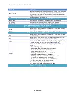
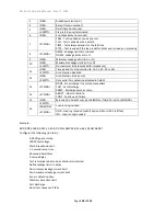
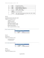
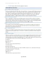
<NR3> 

Dwell time (in seconds) 

<EMPTY> 

Step is to be user terminated 

<NR3> 

Pre-check delay (in seconds) 

<STRING> 

AMPS - Leakage limits are in Amps 
OHMS - Leakage limits are in 


<NR3> 

Minimum Leakage Limit (in A or 

<NR3> 

Maximum Leakage Limit (in A or 

<EMPTY> 

No maximum limit (only valid for impedance) 

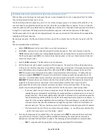
10 

<NR1> 

Time period for arc detection (4, 10, 15, 20, 30 or 40) 

<EMPTY> 

Arc detection disabled 

11 

<NR1> 

Arc detection limit (in mA) 

<EMPTY> 

Only valid if arc detection disabled in field 10 

12 

<STRING> 

NONE - No discharge if next step compatible 
FAST - Fast discharge 
RAMP - Discharge same as ramp 

13 

<STRING> 

ABORT  - Abort on failure 
CONT - Continue on failure 

14 

<NR3> 

Min Load (in Farads), may be <MISSING> if field 15 is also <MISSING> 

15 

<EMPTY> 

Load is not grounded 

<MISSING> 

<STRING> 

GND : Load is grounded (only valid if option HSS or HSS-2 is fitted) 
ISO : Load is not grounded 


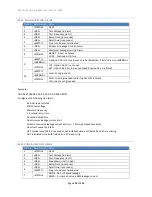
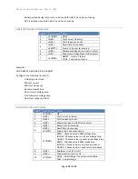
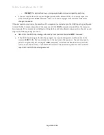
Example 


ADD,DCW,1000.0,0.015,1.5,60.0,0.0,AMPS,0.0,25e-6,4,10,FAST,ABORT 

Configures the following (in order) 


A DCW type test step 
1000V test voltage 
15mA breakdown limit 
1.5 second ramp time 
60 second dwell time 
0 second delay 
Define leakage limits in Amps 
No minimum leakage current limit 
25uA maximum leakage current limit 
4us arc detection time 
10mA arc detection limit 
Fast discharge 
Abort test sequence if fails 
Minimum load during ramp is set to 0 since both fields 14 and 15 are missing 
DUT is isolated since both fields 14 and 15 are missing 


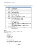
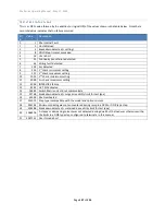
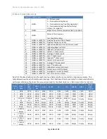
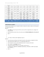
DCIR CONFIGURATION FIELDS  

Field #  Field Format  Value 

<STRING> 

DCIR 

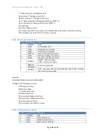
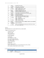
<NR3> 

Test Voltage (in V) 
Summary of Contents for 951i

Page 1: ...VITREK 951 to 957i and 959i OPERATING MAINTENANCE MANUAL...

Page 2: ...erminal Option 13 Power Input Option 13 Rack Mounting Option 13 Output Voltage Current Limiting Options 13 Software 14 Accessories 14 SECTION 2 SAFETY 15 Power and Grounding 15 Terminals and Wiring 15...

Page 3: ...equence 33 Editing an Existing Test Sequence 34 Deleting an Existing Test Sequence 35 Selecting and Running an Existing Test Sequence 35 Displayed Measurement Results 36 Reviewing Test Results after R...

Page 4: ...ing to the DUT 72 Lead Compensation 72 Examples 73 Specifications 73 DC Breakdown Voltage Device Testing BRKDN 74 Actions while Running 74 Configuring 75 Connecting to the DUT 75 Lead Compensation 76...

Page 5: ...92 Configuring 92 Examples 93 Specifications 93 Test Sequence Timing Control PAUSE and HOLD 93 Configuring 93 Examples 94 Specifications 94 SECTION 7 CONNECTING AND CONFIGURING INTERFACES 95 LOCAL and...

Page 6: ...s 107 PASS FAIL and TESTING signals at the end of a Test Sequence 107 HV PRESENT and DWELL Output Signals 107 Examples 107 SECTION 9 PERIODIC MAINTENANCE 109 Cleaning and Inspection 109 Cable Inspecti...

Page 7: ...d Terminator 124 General Response Syntax 124 Delays and Timeouts 125 Multiple Interface Operation 125 Front Panel Operation While Using Interfaces 125 GPIB Bus Commands 126 Device Clear SDC and DCL 12...

Page 8: ...Fields 142 PULSE Configuration Fields 143 BRKDN Configuration Fields 143 PAUSE Configuration Fields 144 HOLD Configuration Fields 144 SWITCH 948i configuration Configuration Fields 145 SWITCH 964i co...

Page 9: ...roduct refinement and possible manufacturer changes to components used in this product Vitrek reserves the right to change any or all specifications without notice This manual has been created with cl...

Page 10: ...ment Vitrek assumes no liability for secondary charges or consequential damages and in any event Vitrek s liability for breach of warranty under any contract or otherwise shall not exceed the original...

Page 11: ...rence between breakdown currents leakage currents and arcing currents and gives you all of the results Advanced measurements When it comes to AC measurements the 95x does not just measure the basics t...

Page 12: ...siderably speeds up testing when multiple test levels are required All of the measurements all of the time The 95x does not just measure what the user has set limits for all measurement results for th...

Page 13: ...e of these options may be fitted in a 951i 952i or 956i Option HSS adds the ability to measure AC or DC breakdown and or leakage into a grounded DUT with down to 10nA resolution Option HSS 2 adds the...

Page 14: ...ut the computer Test results recorded on a computer or on the company network Computer generated multi level test reports Compatibility with a wide range of Windows versions Windows XP through Windows...

Page 15: ...NING DO NOT REMOVE THE POWER CORD FROM THE 95x OR FROM THE SOURCE OF POWER WHILE IT IS OPERATING AT HIGH VOLTAGES THIS WILL REMOVE THE PROTECTIVE GROUND FROM THE CHASSIS OF THE 95x AND THE DUT WHICH M...

Page 16: ...ested The energy in the breakdown is generated by the capacitor itself so there can be no limit on this energy imposed by the 95x WARNING SOME 95x MODELS PRODUCE CURRENTS OF UP TO 40Arms ON THE SOURCE...

Page 17: ...rminal is detected as being significantly different from that expected during the execution of a test step then the test sequence is immediately aborted and any high voltage removed preventing a poten...

Page 18: ...UNIT SHOULD BE IMMEDIATELY TAKEN OUT OF OPERATION AND SERVICED AS SAFETY MAY HAVE BEEN COMPROMISED IF THE UNIT IS TRANSPORTED BETWEEN DIFFERING ENVIRONMENTS AND CONDENSATION IS SUSPECTED THE UNIT SHOU...

Page 19: ...rdware into a bag for safe keeping should they be needed at a later date for bench top usage DO NOT INSERT THE MOUNTING HARDWARE BACK INTO THE BOTTOM OF THE 95x WITHOUT THE FEET INSTALLED THIS MAY DAM...

Page 20: ...st using option AC 30 A shielded coaxial cable terminated in a BNC connector This must be connected to the BNC connector marked EXT FB on the rear panel of the 95x Ensure this connector is securely fa...

Page 21: ...nus the selected element of the menu is highlighted by flashing between the data and blocks These keys allow the user to move the selection point within a menu a The Left and Right Arrow keys are used...

Page 22: ...a SELECT Initiates a menu allowing the user to select a test sequence which has already been defined in the 95x This never requires a password b EDIT Initiates a menu allowing the user to select an e...

Page 23: ...try NOTE during hexadecimal or character data entry certain of the menu keys can be used for entry of the A through F characters b The UNIT key This is used to change the units during numeric data ent...

Page 24: ...an entry into a sub menu then the left side of the line shows descriptive text followed by an ellipsis character The descriptive text is selectable If the user presses the ENTER key while a sub menu e...

Page 25: ...e selection by repeatedly pressing the Up Arrow or Down Arrow keys until the desired selection is displayed The ENTER key terminates the multiple choice data entry and also moves the selection point t...

Page 26: ...the display contrast such that the display is not visible If the display appears to be totally blank then press and hold the Down Arrow key to return it to the visible state if the display appears to...

Page 27: ...ing Press the ENTER key If a non zero password was entered the display now shows a message indicating that the front panel is now locked and returns to the base menu state Otherwise a message is displ...

Page 28: ...95x now displays the build configuration menu an example of which is SERIAL 123456 FIRMWARE v1 12 FP v1 10 MEAS v1 10 DRIVE v1 10 BASE UNIT 951i DC OPTION NONE AC2 OPTION NO AC30 OPTION NO 500VA OPTIO...

Page 29: ...abled as originally purchased When finished reviewing the build information press the EXIT key to return to the main configuration menu and then press EXIT again if no additional configuring is to be...

Page 30: ...enu and save the settings RETURNING ALL CONFIGURATION SETTINGS TO FACTORY DEFAULTS The user may return all configuration settings to the factory default settings as follows Ensure that the display ind...

Page 31: ...l step types are available for use in this type of test sequence o While testing using these the user may not alter the voltages currents or frequencies being applied by the 95x o Certain step types a...

Page 32: ...SAFETY ENABLED MIN LOAD ENABLED MAX DISCHARGE 200mA The user may navigate this sub menu and change the displayed settings as required o START BEEP This allows the user to set the volume of the beep so...

Page 33: ...mum loading detection as needed o MAX DISCHARGE This sets the maximum current which will be used by the 95x when discharging a load at the end of a DCez DCW or DCIR type test step A value between 1 an...

Page 34: ...sting name by pressing the Up Arrow key followed using the Up Down Left and Right keys to change select each character and the user may use the numeric keys to directly enter numeric characters Press...

Page 35: ...ECT TEST SEQUENCE 2 95x LINE HYPOT As needed change the test sequence number to select the desired test sequence by using the Up Arrow or Down Arrow keys or using the numeric keys then press the ENTER...

Page 36: ...sing the UNIT key which toggles between all measurement results available for that test type See Displayed Measurement Results If certain types of failure occur then a temporary display is shown simil...

Page 37: ...ssing the VIEW key if the READY indicator is illuminated indicating that the test sequence is still ready to be run If the test sequence failed then the review is initiated at the first failed step ot...

Page 38: ...mum load for this test step was not achieved during ramp in a DCW or DCIR type step which caused the step to fail 01 01d SWITCH SWITCH FAILED The 95x could not communicate with an external switch matr...

Page 39: ...ed measurement limit failure then a failure message is displayed instead By default the final measurement result is shown in the lower portion of the display This can be changed to the minimum MIN max...

Page 40: ...ame on all printouts o AUTO TEST REPORT This allows the user to set whether the 95x will automatically print a test report when a test sequence terminates YES or not NO The user can also command a pri...

Page 41: ...LINE HYPOT As needed change the test sequence number to select the desired test sequence by using the Up Arrow or Down Arrow keys or using the numeric keys and then press the ENTER key The selected te...

Page 42: ...e Testing DCez DCW and DCIR 20V 6 5kV 20V 6 5kV 40V 11kV 40V 11kV 40V 11kV 20V 6 5kV 75V 15kV No Pulsed Voltage Withstand Testing Opt PMT 1 only PULSE 50V 8kV 50V 8kV 50V 8kV 50V 8kV 100V 10kV No 50V...

Page 43: ...in as little as a few milliseconds with the 95x Note that this is different to static discharge pulse testing If AC testing is to be performed it is recommended that the frequency should be the expect...

Page 44: ...according to the requirement and either disable the leakage limits entirely only for the ACW type or set the maximum leakage limit equal to or higher than the breakdown limit BREAKDOWN CURRENT A break...

Page 45: ...he reactance of the DUT typically capacitance The total RMS AC current is the scalar formed by combining the in phase and quadrature vector currents In phase and quadrature currents can be of either p...

Page 46: ...e most of the energy for the arcing and there may be little if any HF current flow from the DUT In these cases it may not be possible to detect arcing by current flow This is generally not the case fo...

Page 47: ...period can be programmed to be skipped and the next step started at this steps dwell voltage level if the next step is an ACez ACW or ACCAP type CONFIGURING An example ACez type menu is as follows Se...

Page 48: ...installed o YES This selection indicates that the DUT is grounded and the breakdown and or leakage currents are to be measured to ground The 95x will use the current in the HV terminal to measure leak...

Page 49: ...during the dwell period o The highest maximum limit which can be entered is determined by the maximum loading current which the specific 95x model and option content can continuously supply at the con...

Page 50: ...deciding which point on the DUT to connect to the HV terminal and which point to connect to the RETURN terminal the user should consider that only the voltage on the RETURN terminal is safe at all tim...

Page 51: ...o the point on the DUT which is to be tested It is expected that the DUT is grounded and that the breakdown and or leakage is being tested to ground For safety reasons or if unsure if the DUT is groun...

Page 52: ...st step When performing a lead compensation the normal connections to the 95x should be in place with the wiring positioned normally only the DUT itself should not be connected CAUTION High voltages w...

Page 53: ...is known to have little leakage this could be set lower RAMP 1 00sec As required DWELL 1 00sec As required Test 1 NONE No leakage testing required Test 2 NONE No leakage testing required ARC DETECT 4u...

Page 54: ...bove 1700Vrms Option 500VA 100Hz 100mArms 50mArms resistive reduce by 0 14mA per V above 5425Vrms 500VA Above 65mArms has a limited test time e g 1sec at 100mArms Option 500VA 400Hz 85mArms 50mArms re...

Page 55: ...1uA accuracy 30usec detection time 3msec response time typically 500usec Leakage Current 0 0nA to 200mArms RMS In phase or Quadrature Greater of 1 cycle or 10ms measurement period RMS 0 5 10nA 0 15nA...

Page 56: ...a DUT does not exhibit breakdown or optionally arcing in the presence of an applied DC voltage and optionally to test that the DUT leakage current or impedance is within user set limits All of these...

Page 57: ...ltage is reduced to zero in the programmed time or at the programmed rate If the actual voltage significantly lags the expected voltage during the discharge then discharge circuitry is automatically e...

Page 58: ...ut voltages from the specific 95x or above the maximum voltage limit set by the user in the CNFG TEST USER MAX DCV setting DUT GROUNDED Only available if option HSS or HSS 2 is installed This selectio...

Page 59: ...following o For settings of below 1nF there must be enough charging current flow during ramp for the set minimum capacitive load to be successfully detected For a DUT GROUNDED setting of NO or option...

Page 60: ...fail status for leakage is based upon the final measurement taken at the end of the dwell period o STDY The dwell period will be automatically terminated when the leakage is within the allowable limi...

Page 61: ...and any dwell leakage current or resistance limits defined in such a step will be ignored and the ramp phase of the next step is immediately started after the end of the preceding stage ramp There ar...

Page 62: ...nt on the DUT which is connected to the RETURN connection When deciding which point on the DUT to connect to the HV terminal and which point to connect to the RETURN terminal the user should consider...

Page 63: ...ility that a disconnected DUT will erroneously pass a test There is always some amount of capacitance within the load which will always cause an amount of current to flow during ramp when properly con...

Page 64: ...he panel because of its capacitance This is accomplished in a single step as follows Seq 1 Step 1 DCW Different breakdown and leakage limits so use DCW LEVEL 2500 0V As required BREAKDOWN 20 00mApk Mu...

Page 65: ...a minimum capacitance of 1uF and a maximum of 4uF the current at 10V 20Hz will be between 1 25 and 5mArms This requires that the Opt AC 2 option be installed This is accomplished in three steps as fo...

Page 66: ...um loading is restricted to a maximum of 5mA Capacitive loading is only limited by the maximum ramp time 9999 9sec and the maximum load current typically this is a 1F load 951i 952i and 956i 50mA redu...

Page 67: ...Compensation 1 of error RESISTANCE MEASUREMENTS DUT ISOLATED Measurements are performed between the HV and RETURN terminals of the 95x For applied voltage breakdown current and arc current accuracies...

Page 68: ...0G 100K 50G 1 1 R 1 5G 100K 25G 1 1 R 700M 2500V 250K 1 5T 1 1 R 50G 250K 60G 1 1 R 1 75G 250K 25G 1 1 R 800M 5000V 500K 3T 1 1 R 100G 500K 60G 1 1 R 1 8G 500K 25G 1 1 R 800M 10000V 1M 6T 1 1 R 200G 1...

Page 69: ...10K 300M 1 5 R 10M 10K 300M 1 5 R 10M 100V 10K 600M 1 4 R 20M 10K 600M 1 4 R 19M 10K 600M 1 4 R 18M 250V 10K 1 5G 1 3 R 45M 10K 1 5G 1 3 R 45M 10K 1 4G 1 3 R 40M 500V 10K 3G 1 3 R 90M 10K 2 75G 1 3 R...

Page 70: ...alues in real time during discharge Selection Criteria 400W power 400J energy 7500V current CNFG TEST MAX DISCHARGE setting 951i 952i 956i Nominal loading 9 5K or 40K 953 4i and 957i Nominal loading 9...

Page 71: ...is 40ms CONFIGURING An example PULSE menu is as follows Seq 1 Step 1 PULSE LEVEL 200 0V POLARITY UNIPOLAR BREAKDOWN 150 0mApk RAMP 1 0msec HOLD 1 5msec ARC DETECT 4us 10mA ON FAIL ABORT SEQ LEVEL All...

Page 72: ...m the 95x to abort the entire sequence ABORT SEQ or only this step CONT SEQ if this step fails any of its checks A safety related failure or a user abort STOP button always aborts the entire sequence...

Page 73: ...as little capacitance ARC DETECT 4us 10mA Optional ON FAIL ABORT SEQ The actual test voltage may not have achieved the required test voltage with sufficient accuracy When reviewing the results the act...

Page 74: ...ltage is ramped at the user set maximum ramp rate to an automatically selected voltage level between 50 and 90 of the minimum breakdown voltage limit setting If the user set breakdown current limit oc...

Page 75: ...rates It is not recommended to set ramp rates of more than 10 times the lowest expected breakdown voltage per second e g if the lowest expected breakdown voltage is 500V then the highest recommended...

Page 76: ...ther otherwise excessive ground loop currents may flow potentially damaging the 95x LEAD COMPENSATION Performing a lead compensation for this type of test step has no affect the test step is performed...

Page 77: ...hassis ground bond testing See DC Low Resistance Testing Low If the resistance is between 1u and 10 and it is allowable or required to measure using AC at a user defined current between 0 1A and 40Arm...

Page 78: ...ser abort STOP button always aborts the entire sequence CONNECTING TO THE DUT See Terminals and Wiring for general wiring and safety recommendations The 95x requires that the DUT at least that portion...

Page 79: ...stance measured is that between the innermost connection points to the DUT i e between the SENSE and SENSE connections If any wire has more than nominally 100 of resistance then the test is failed wit...

Page 80: ...ired ON FAIL ABORT SEQ Example 2 It is required to test that a DUT chassis is bonded to its grounding terminal with no more than 0 1ohm of resistance This is accomplished in a single step as follows S...

Page 81: ...ROUND BOND TESTING GBEZ AND GB These types are primarily for testing resistance values from a few microohms up to 8 at a user set AC test current between 0 1 and 40Arms typically for ground bond testi...

Page 82: ...of zero length For the GB type the discharge period can optionally be skipped if the next step is also a GB type CONFIGURING An example GBez type menu is as follows Seq 1 Step 1 GBez LEVEL 25 000A 60...

Page 83: ...ng a zero value for it o In Phase and Quadrature measurements can be of either polarity the limits are applied to the measurement without regard to polarity DISCHARGE Only available for the GB type Al...

Page 84: ...SENSE wires together for at least the majority of the wire length Alternatively if the user maintains at least a spacing between each wire and all other wires then these effects are also reduced Simi...

Page 85: ...ation the impedance limits are not enforced otherwise the test step is executed normally During a lead compensation the SOURCE SENSE SOURCE and SENSE wires should be solidly shorted together at the DU...

Page 86: ...level as that test is the most demanding It is desired to perform all tests within less than 0 5 second to ensure production throughput This is accomplished in three steps as follows Seq 1 Step 1 GB...

Page 87: ...of final value in 0 1sec 2 cycles Test Frequency 40Hz to 500Hz 0 1 accuracy Test Waveform Sinewave 1 3 1 5 Crest Factor Compliance 8Vrms 0 015V A max compliance at test frequencies 75Hz For line volta...

Page 88: ...ltage on the HV terminal relative to ground and makes the result of this measurement available to the user if not required then this can be ignored Optionally the user can also detect arc currents and...

Page 89: ...protect the system from high current flows in the event of a DUT failure The example above shows a typical DUT ground leakage connection between the DUT and the 95x The DUT line and neutral connection...

Page 90: ...rm quickly Delay 0 00sec Already connected so no delay needed Lim 0n 5 000mA Per the requirement ARC DETECT OFF Not required so disabled ON FAIL ABORT SEQ Seq 1 Step 2 DCI DC leakage required so use D...

Page 91: ...CIFICATIONS Specifications are valid at the 95x terminals for 1 year at ambient temperatures within 5C of calibration temperature add 5 of accuracy specification per C outside of this All specificatio...

Page 92: ...his period until the user set post switch delay has expired This period allows for relay and wiring settling after changing the relay states As soon as the delay has expired the next test step in the...

Page 93: ...s example 1 above but using a Vitrek 948 Since a Vitrek 948 is being used a 0 25sec post switch delay is needed The 56 bit code for the required state is splitting the binary into groups of 8 bits for...

Page 94: ...5x will wait forever for user interaction to occur EXAMPLES Example 1 The user wishes to program a 1 second pause into a test sequence to allow for wiring settling between two steps A PAUSE step is co...

Page 95: ...to return the 95x into the local state the user should press the CNFG key on the 95x front panel If the 95x has been enabled to return to the local state by the controlling interface then the REMOTE i...

Page 96: ...ingle Vitrek 948i Switch Matrix unit is being controlled by the 95x via the RS232 serial interface The RS232 BAUD setting is ignored if this is selected 964 SERIAL A single Vitrek 964i Switch Matrix u...

Page 97: ...when using the VICL interface CONTROLLING THE 95X BY THE RS232 INTERFACE NOTE the RS232 interface can only be used for a single purpose it cannot be used for both controlling an external Switch Matri...

Page 98: ...itrek connect the RS232 port on the 95x rear panel to the RS232 Serial port of a computer The user may supply their own cable in which case it should be a 9 wire female female null modem cable capable...

Page 99: ...auto selected MDI MDIX Auto selected Protocols ICMP ARP DHCP TCP IP IPv4 only TCP Port 10733 Remote Connections Only one remote connection is allowed at any given time Connector RJ45 Cable required C...

Page 100: ...R key The Ethernet sub menu allows the user to configure the 95x for the local network An example of this sub menu is as follows USE DHCP YES IP 000 000 000 000 SNET 000 000 000 000 GTWY 000 000 000 0...

Page 101: ...nts above Vitrek has tested the 95x with the HP OfficeJet Pro 8000 Series and the HP LaserJet 2420 The 95x is generally not compatible with multi purpose printers e g All in One types CONNECTING The p...

Page 102: ...TER DISCONNECTED Indicates that the USB cable became disconnected PRINTER USB BUS ERROR Indicates that an unrecoverable USB bus error occurred The 95x automatically reinitializes the USB bus after thi...

Page 103: ...ety interlock is opened Allow the 95x to illuminate external safety indicators CONNECTOR AND PINOUT The DIO signals are available at the rear panel of the 95x in the 15 pin connector identified as DIG...

Page 104: ...waiting for user interaction e g in a HOLD step or programmed for a user terminated test step If the SEQUENCE input signals are not used to select a sequence then a sequence must have been already ma...

Page 105: ...olarity i e active high for INTERLOCK and active low for ABORT CAUTION changing the active level of the START signal may cause the 95x to detect a change in the START signal from the inactive to the a...

Page 106: ...16V 14V minimum so may be used to directly drive a relay When using a digital output to drive a 12V relay coil or indicator the user should consider that each output has a nominally 3 2mA current flo...

Page 107: ...is valid and started correctly otherwise remains inactive ABORTING WITH THE ABORT OR INTERLOCK SIGNALS If enabled and the ABORT signal is active for 5ms then any running test sequence is aborted If en...

Page 108: ...but the user wishes to always run sequence 3 when the external start switch is activated The user will not need to select a test sequence from the front panel In this case the mechanical switch shoul...

Page 109: ...returning it to use FAN FILTER CLEANING With power completely removed from the 95x visually inspect the cleanliness of the fan filter The fan filter is located on the rear panel of the 95x near the po...

Page 110: ...re Ensure that the display indicates that the 95x is in the base menu state i e the display shows the date and time If necessary press the STOP button to abort a menu and return to the base menu state...

Page 111: ...ations Periodic Verification Adjustment Verification This is the most complete strategy but is also the costliest in time The time cost can be reduced by performing the initial verification and then o...

Page 112: ...al 30mAdc current for a 4 1 accuracy ratio the 95x specification is 2m and 952i 4i 9i only an impedance of less than 1 625u at 5Arms 60Hz current for a 4 1 accuracy ratio the 952i 4i 9i specification...

Page 113: ...isted above NOTE this short circuit must have less than 5uV of thermally induced voltage the user may need to wait for some time after making connections Ensure that the short circuit is properly inse...

Page 114: ...5x terminals The 95x internal current source is from the SOURCE terminals and the voltage sense uses the SENSE terminals ensure that the resistor is connected with the terminals and terminals correctl...

Page 115: ...e equipment needed to perform performance verification is highly specialized and may not be available to many users Making very high voltage measurements with high precision requires special skills an...

Page 116: ...rds of values 100K 10K 100 and 1 capable of being connected using a 4 wire configuration and accuracies which yield the desired error ratio to the 95x series accuracy see the Low Ohms Resistance Verif...

Page 117: ...measure the actual voltage and record it checking against the 95x specification When the user is satisfied that the step has been completed the user should press START to continue or STOP to abort the...

Page 118: ...on the voltage being measured ENSURE THAT THE MEASURING DEVICE AND WIRING IS CAPABLE OF WITHSTANDING THE VOLTAGE LEVEL PRIOR TO PRESSING THE START SWITCH AT EACH STEP The table below shows the fullest...

Page 119: ...ting of the resistances requested for verification and the 95x specification at each resistance value When prompted for each step the user should either Press the START switch to perform the verificat...

Page 120: ...5x The milli ammeter is used to determine the actual load current the 95x displays the value which it is measuring The table below shows the listing of the resistances requested for verification the m...

Page 121: ...Press STOP to abort the entire sequence During each step the user should note the displayed measurement on the 95x display and record the difference between this measurement and the micro ammeter rea...

Page 122: ...characters STRING is a general string of ASCII characters NR1 is an integer numeric NR3 is a floating point numeric BOOL is a boolean indicating true or false GENERAL COMMAND SYNTAX Every command tak...

Page 123: ...erally has a specific effect defined in the description for each command b BOOL This can be the single character Y or 1 denoting a true state or the single character N or 0 denoting the false state th...

Page 124: ...acter Any character immediately following a character is taken literally and included in the STRING and the character is discarded FIELD SEPARATOR Fields are separated by the comma character COMMAND S...

Page 125: ...ys uppercase character o A single polarity character either or indicating the polarity of the exponent o Two decimal digit characters indicating the value of the exponent For clarity in engineering us...

Page 126: ...n the RS232 and Ethernet interfaces to allow the user to remotely return the front panel to the LOCAL state This command must be the last command in a set of commands GPIB BUS COMMANDS Most standard G...

Page 127: ...y being performed The value of this status bit is dynamic i e its value can change without user interaction Bit 3 decimal value 8 binary value 00001000 set when a test sequence is completed cleared wh...

Page 128: ...is detected Bit 5 decimal value 32 binary value 00100000 set when an ARC current over limit has been detected Bit 6 decimal value 64 binary value 01000000 not used always 0 Bit 7 decimal value 128 bi...

Page 129: ...n Fields GBez Configuration Fields GB Configuration Fields Low Configuration Fields ACCAP Configuration Fields ACI Configuration Fields DCI Configuration Fields PULSE Configuration Fields BRKDN Config...

Page 130: ...f the active test sequence Active Test Sequence Status Query Commands RUN Responds with a BOOL indicating if the active test sequence is being run 1 or not 0 SEQ Responds with a NR1 which is the activ...

Page 131: ...The response contains one character for each defined test step P passed F failed Not performed In process STEPRSLT NR1 Responds with a set of fields giving the complete set of results for the specifi...

Page 132: ...fail on arc detection setting FASTRERUN NR1 Configures how a test sequence may be rerun from the front panel 0 enable fast rerun 1 enable fast rerun if pass 2 disable fast rerun FASTRERUN Responds wi...

Page 133: ...e during future test sequences VLIMIT AC Responds with the NR3 maximum AC Voltage setting Identification Commands IDN Responds with a set of fields describing the product see IDN Response Fields OPT R...

Page 134: ...unded valid if option HSS is fitted ISO Load is not grounded Example ADD ACEZ 1000 0 60 0 1 5 60 0 0 0 0 005 ABORT Configures the following in order An ACez type test step 1000V test voltage 60Hz test...

Page 135: ...NR3 2nd Minimum Leakage Limit in A or EMPTY Only valid if no 2nd checked leakage 12 NR3 2nd Maximum Leakage Limit in A or EMPTY No 2nd maximum limit only valid for impedance or no 2nd checked leakage...

Page 136: ...econds 4 NR3 Dwell time in seconds EMPTY Step is to be user terminated 5 NR3 Minimum Leakage Limit in A 6 NR3 Maximum Leakage Limit in A 7 STRING ABORT Abort on failure CONT Continue on failure 8 EMPT...

Page 137: ...inue on failure 14 NR3 Min Load in Farads may be MISSING if field 15 is also MISSING 15 EMPTY Load is not grounded MISSING STRING GND Load is grounded only valid if option HSS or HSS 2 is fitted ISO L...

Page 138: ...on limit in mA EMPTY Only valid if arc detection disabled in field 11 13 STRING NONE No discharge if next step compatible FAST Fast discharge RAMP Discharge same as ramp 14 STRING ABORT Abort on failu...

Page 139: ...Bez type test step 25A test current 60Hz test frequency 60 second dwell time No minimum voltage drop 0 1V maximum voltage drop Abort test sequence if fails GB CONFIGURATION FIELDS Field Field Format V...

Page 140: ...ce Fast discharge Abort test sequence if fails LOW CONFIGURATION FIELDS Field Field Format Value 1 STRING LOWOHM 2 BOOL 1 or Y Test using 2 wire mode 0 or N Test using 4 wire mode 3 NR3 Test time in s...

Page 141: ...ST Fast discharge RAMP Discharge same as ramp 14 STRING ABORT Abort on failure CONT Continue on failure 15 EMPTY Option AC 30 is not used may only be MISSING if field 16 is also MISSING MISSING STRING...

Page 142: ...ction disabled in field 6 8 STRING ABORT Abort on failure CONT Continue on failure Example ADD ACI 5 0 0 0 0 0 50e 6 ABORT Configures the following in order An ACI type test step 5 second test time 0...

Page 143: ...LAR Bipolar 4 NR3 Ramp time tr in seconds 5 NR3 Hold Time th in seconds 6 NR3 Breakdown Current Limit in A 7 NR1 Time period for arc detection 4 10 15 20 30 or 40 EMPTY Arc detection disabled 8 NR1 Ar...

Page 144: ...1 1000 0 500 0 600 0 ABORT Configures the following in order A BRKDN type test step 1mA test current level 1000V sec initial ramp rate 500V minimum breakdown voltage 600V minimum breakdown voltage Abo...

Page 145: ...nk 2 set to hexadecimal 00 Bank 1 set to hexadecimal 00 Bank 0 set to hexadecimal 00 SWITCH 964I CONFIGURATION CONFIGURATION FIELDS Field Field Format Value 1 STRING SWITCH 2 NR3 Pre switch delay in s...

Page 146: ...95x Series Operating Manual May 17 2022 Page 146 of 155 Bank 4 set to hexadecimal 00 Bank 3 set to hexadecimal 00 Bank 2 set to hexadecimal 00 Bank 1 set to hexadecimal 00 Bank 0 set to hexadecimal 00...

Page 147: ...eck maximum setting 10 1024 2nd check minimum setting 11 2048 2nd check maximum setting 12 4096 INTERLOCK failure 13 8192 HV TRIP activated 14 16384 Switch Matrix unit did not communicate 15 32768 Bre...

Page 148: ...EMPTY Last arc current in Amps Not all of the above fields are valid for each step type fields which are not used for a step type are empty The table below shows the valid fields for each step type Th...

Page 149: ...ACez ACW DCez DCW DCIR GBez GB Low ACCAP ACI DCI BRKDN PULSE PAUSE HOLD SWITCH PROGRAMMING EXAMPLE If the user wishes to be able to send a command to the 95x to test that the interface is active and f...

Page 150: ...nd EMPLOY A TIMEOUT ON ALL ACTIVITIES On all interfaces the 95x has full handshake capabilities so both commands and responses can be held up for short periods of time The user must employ timeouts fo...

Page 151: ...e STEP or RUN Commands can be used the STEP command is recommended as it provides more information in the response If needed the user could also program MEASRSLT Command s to extract actual measuremen...

Page 152: ...il the CONT command is received from the computer As an example if the computer is controlling switching which needs to be altered during execution the user would program the following during executio...

Page 153: ...t make any changes to either the 95x QuickTest Pro or their test sequences because of these changes An updated version of QuickTest Pro using some of the new features may be available contact Vitrek f...

Page 154: ...etting a minimum load for each step see DCW Configuration Fields or DCIR Configuration Fields for details If the extra field is missing i e the user has not altered their software to support v2 02 the...

Page 155: ...hanges are needed o If option HSS or HSS 2 is fitted then the user should note that several menus and interface commands have altered to enable the user to control its usage and that option HSS or HSS...

Reviews: