95x Series Operating Manual - May 17, 2022
Page
77
of
155
VOLTAGE AND CURRENT ACCURACY
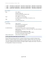
Breakdown Voltage Accuracy <(± 0.5% ± 1.5V) (add an additional ±5V if option HSS-2 installed)
<30usec detection time
<10msec response time
Breakdown Current Accuracy <(± 1.5% ± 3uA)
<30usec detection time
<10msec response time
TEST TIMING
Ramp and Search
<50kV/sec , ± 15% ± 10ms accuracy
CHOOSING WITHIN THE RESISTANCE TESTING GROUP
The user may choose for the 95x to test the resistance of a DUT using one of three activities-
•
If the resistance to be tested is more than 100K
Ω
- use the DC Voltage Withstand capability of the 95x to
measure the resistance of the DUT. This can accommodate resistances of below 10K
Ω
to over 1T
Ω
using a
fixed DC Voltage across the DUT. Typical applications for this include insulation resistance and higher
value resistor component testing. See DC Voltage Withstand and Leakage Testing (DCez, DCW and DCIR).
•
If the resistance is between 1m
Ω
and 100K
Ω
and it is allowable to measure using DC at a current of up to
50mA and voltages up to 5V - use the DC Low Resistance capability of the 95x. Typical applications for this
include component testing, cable resistance testing, and (if allowed by the safety standard) chassis ground
bond testing. See DC Low Resistance Testing (Low
•
If the resistance is between 1u
Ω
and 10
Ω
and it is allowable (or required) to measure using AC at a user
defined current between 0.1A and 40Arms and a voltage up to 8Vrms (11.5Vpk) - use the AC Ground Bond
capability of the 95x (not all models have this capability). Typical applications for this include chassis
ground bond testing and cable resistance testing at high currents. The 95x also offers the ability to
independently measure the in-phase (resistance) and quadrature (reactance) components of the DUT
while maintaining stability with inductive loads for component testing applications. See AC Ground Bond
Testing (GBez and GB).
DC LOW RESISTANCE TESTING ( LOW
Ω)
This type is primarily for testing resistance values from a few milliohms up to 100K
Ω
using either 2-wire or 4-wire
measurement methods.
ACTIONS WHILE RUNNING
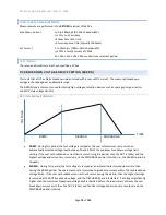
This type of test step is performed using a single measurement period. The user may program for a delay at the
start of the test period before the resistance measurement is checked against the limits. This can be used to allow
for capacitance in parallel with the DUT.
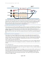
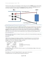
When programmed to perform a 4-terminal measurement, the 95x continuously performs a set of checks that the
DUT is correctly wired to the 95x throughout the test period.
CONFIGURING
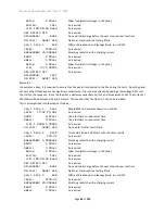
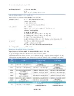
An example Low
Ω
menu is as follows
–
Seq 1 Step 1 LOW
2/4-WIRE: 4-WIRE

