Front Panel Controls and Connections
11
Front Panel Controls and Connections
This chapter discusses the basic use of the various controls, connectors and indi-
cators on the front panel of the 2000I, 2000M, 2000IN and 2000MN DC power
source instruments.
Before using your instrument refer to the text on
Charging
the Battery.
For a
complete discussion on the methods used to perform specif-
ic tasks refer to
Front Panel Operation.
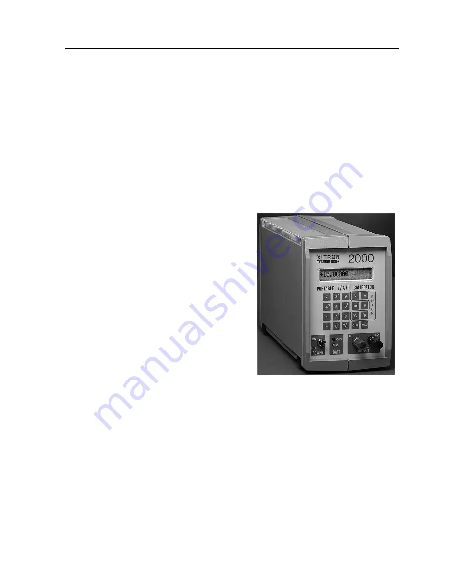
Display
The 2000 Families DC power source
instrument display is a 16 character,
single line reflective liquid crystal
(LCD). This display shows selectable
status or the present output of the
instrument.
During interactive sequences the dis-
play enables you to select a mode and
enter a value for your desired output,
calculation or measurement
.
The 2000 Instrument
“POWER” Switch
This toggle switch controls the power applied to the circuitry in the instrument.
Note that the charging module is always connected to the charging control circui-
try in the instrument, thus the POWER switch does not control the charging of the
battery.
Summary of Contents for Xitron 2000 Series
Page 1: ...USER GUIDE 2000 Family DC Temperature Source Instruments...
Page 2: ......
Page 18: ...2000I 2000M Instrument s User Guide Revision B 18...
Page 42: ...2000I 2000M Instrument s User Guide Revision B 42...
Page 47: ...Using the Memory Options 47...
Page 60: ...2000I 2000M Instrument s User Guide Revision B 60...
Page 91: ......
Page 92: ...2000I 2000M Instrument s User Guide Revision B 92...
Page 95: ...Appendix B General Specifications 95...
Page 97: ...Password Page 97...

