background image


Applications 53 


Using the Adjust Mode to Check Calibration 

For this application the “Adjust” mode of operation is used to measure the error 
of the equipment being tested. To test, simply set the calibrator to the required 
output level and then adjust the output level until the equipment being calibrated 
reads the correct value. The display of the calibrator will then show the actual 
error of the unit. When one unit has been calibrated, remove the calibrator from 
the “Adjust” mode. The output level will then revert to the nominal output level 
in readiness for calibration of the next unit. 

Calibrating Transducer Systems: 

Connect the 2000 instrument in parallel with a 4 – 20mA or a 1 – 5V transducer 
output to modify the transducer’s indicated output. 

Adjusting Calibration of Multiple Units 

The drive capabilities of the 2000 instruments are sufficient to adjust the calibra-
tion of multiple units of equipment simultaneously. In voltage mode this is 
achieved by connecting all the units to be calibrated in parallel. 10 to 20 units can 
be adjusted simultaneously at voltages above 220mV. At voltages below 220mV 
the 50

 output impedance of the 2000 instruments becomes significant.  

If the units being adjusted have 10M

 (or lower) input impedance then a correc-

tion has to be made for the output impedance of the 2000 instrument.  


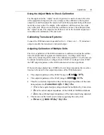
The output impedance of the 220mV range is 

45.048


0.1%


The output impedance of the 22mV range is 

49.998


0.1%

.  


Thus the correction required to allow for the input impedance of the units 
being adjusted is: 

Correction = (Z

O

 + Z

IN 

) / Z

IN


Where the required output voltage should be multiplied by Correction. 


Z

O

 is the actual output impedance of the 2000I or 2000M instrument. 


Z

IN

 is the combined input impedance of the instrument being adjusted. 


The increase in the limits of error due to applying this correction 
 is: 

Error = ( ( 1000 + EZ

IN

) * Z

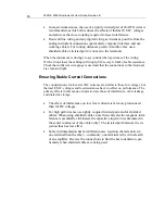
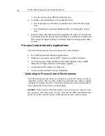
O

) / Z

IN


Summary of Contents for Xitron 2000 Series

Page 1: ...USER GUIDE 2000 Family DC Temperature Source Instruments...

Page 2: ......

Page 3: ...as a result of misuse improper repair or abnormal conditions or operations repairs will be billed at cost Vitrek assumes no responsibility for its product being used in a ha zardous or dangerous mann...

Page 4: ...ns proprietary information which is subject to change without notice The product displays and instructional text may be used or copied only in accordance with the terms of the license agreement is a t...

Page 5: ...ys __________________________________________ 13 Key _______________________________________________ 13 Arrow Keys ____________________________________________ 13 Multiplier Keys _____________________...

Page 6: ..._________ 29 Adjusting Output Level or Simulated Temperature _____________ 30 Increasing or Decreasing Output Level_______________________ 31 Changing Adjustment Value _______________________________...

Page 7: ...________________________ 75 Selecting RS232 ________________________________________ 76 RS232 Handshake Lines __________________________________ 76 IEEE488 Interface Option ___________________________...

Page 8: ...Time _________________________________________ 94 Environmental __________________________________________ 94 Isolation_______________________________________________ 94 Computation _________________...

Page 9: ...a units text string which enables the calibration of four 20mA loops in the actual units and scaling of the transducer Optional IEEE488 or RS232 isolated interfaces further enhance the 2000 instrument...

Page 10: ...in field calibration requirements of the process control indus try Portable for use in remote sites Functions as a transducer replacement with computed output levels and enabled data entry in psi KPa...

Page 11: ...Display The 2000 Families DC power source instrument display is a 16 character single line reflective liquid crystal LCD This display shows selectable status or the present output of the instrument D...

Page 12: ...y is being charged Upon full charge this light extinguishes Green OK Light This green light LED illuminates when the power switch is turned on for 2000I and 2000M For the 2000IN and 2000MN products th...

Page 13: ...hen not in a numeric entry then the output level is re versed i e the output polarity is changed Arrow Keys During a menu selection and during the Adjust mode the 2 4 6 and 8 keys are arrow keys which...

Page 14: ...line on the keypad These keys are used to output in the selected units which terminates a numeric entry They can also select the displayed action For example in Measure mode 2000M only the V A C and...

Page 15: ...n that provided by Vitrek ensure the selected charger s output voltage is 12V at 1 5A and the center conductor is positive polarity and uses 2 5mm DC plug Compensated Thermocouple Connection This ther...

Page 16: ...instrument The connections are as follows 1 Data Carrier Detect Output from instrument 2 Transmit Data Output from instrument 3 Receive Data Input to instrument 4 Data Terminal Ready Input to instrum...

Page 17: ...is considerably shortened when the IE BAT Interface is enabled thus it is highly recommended that this switch be maintained in the OFF down position whenever this interface is not being used The IE BA...

Page 18: ...2000I 2000M Instrument s User Guide Revision B 18...

Page 19: ...k During shipping or storage the battery may discharge We recom mend the battery be recharged for at least 12 hours prior to its initial use Use the charging unit provided Vitrek to charge the interna...

Page 20: ...he instrument s rear panel and plugging the Charging Module into the local AC supply Ensure that the voltage rating of the Charging Module is in accordance with the local AC supply voltage Note For th...

Page 21: ...it available when making this order MS2000 This option delivers a full service manual incorporating schematics assembly diagrams fault diagnosis aids and full servicing information If not included at...

Page 22: ...obile battery This latter method for recharging the internal battery in the instrument yields the useful feature of allowing you to recharge the instrument from an automobile e g the cigarette lighter...

Page 23: ...covered in the Us ing the Memory Options chapter and calibration is covered in Calibration and Maintenance Additional 2000 instrument uses are covered in the Applications chapter Initial Power Applica...

Page 24: ...input terminals when the 2000M instrument is set to the Measure mode 2 In cold junction compensation mode CJC the output connectors are wired in parallel with a female rear panel mounted connector Dis...

Page 25: ...mode When Use Active CJC displays when the instrument is in Passive CJC or Operate mode When Use Passive CJ displays the instrument is actually in Active CJC Selecting Operate or Standby In Standby m...

Page 26: ...of the display and the remain ing portions of the display will be blank The cursor will automatically move to under next possible character entry point showing the position into which the next key pr...

Page 27: ...following paragraphs for an explanation Direct Entry of Required Output Level When the display shows the actual output level and status the required output level may be entered Key in the numeric data...

Page 28: ...capabilities of the instrument then the closest possible output level is selected and a warning message is displayed for approximately two seconds Changing Displayed Multiplier The output level is di...

Page 29: ...display format used for temperature simulations also includes infor mation regarding the thermocouple type Examples of the format used are 1000 00 C R and 1000 00 F R In both cases the selected thermo...

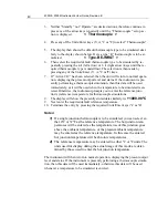
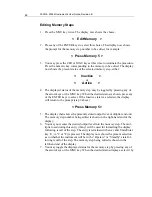
Page 30: ...each modified output level of the equipment being calibrated This function allows for any error in the equipment to be highlighted This section describes the method used to perform this action To acce...

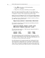
Page 31: ...ways displays using the lowest possible mul tiplier therefore A voltage deviation of up to 999uV is displayed using the multiplier A voltage deviation of up to 999mV is displayed using the m multiplie...

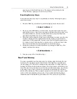
Page 32: ...e present display window is ignored Terminating Adjust mode Terminating the Adjust mode of operation is achieved using the MNU key once and arrow keys repetitively Here the display shows the action as...

Page 33: ...he desired initial output level terminating the entry by press ing the Units Enter keys V or A as required The instrument returns to normal Operation displaying the present output level and status The...

Page 34: ...output level cannot exceed 2 2V irrespective of the entered value As before when programming values which exceed the in strument s output level capability the 2000 instruments will automatically go t...

Page 35: ...d or enter the desired data and units 6 The display then prompts you to enter User Data A and displays the presently stored data Press any units key if this data is to be retained or enter the de sire...

Page 36: ...key used to terminate the entry is discarded 2 While a multiplier key may be used during the entry this does not affect the display format it is used to scale the entered data however 3 The Adjust mo...

Page 37: ...ure mode The instrument will then begin measuring the applied voltage converting it into the computed temperature for the selected thermocouple type To display the measured voltage Press the V key To...

Page 38: ...lable in the 2000M only Thermocouple Simulation and Measurement Set Up The 2000M instrument s thermocouple simulation capability is achieved by set ting the desired simulation parameters and then comm...

Page 39: ...age or current output level command or by sending the V command string without any numeric data In this case the output level simply stays at the previously Calculated voltage but terminates thermocou...

Page 40: ...tered Otherwise the instrument prompts you to enter the reference junc tion s reference temperature for thermocouple simulations 8 The display will show the presently stored data similarly to 1000 00...

Page 41: ...t Capacity Specifications Deselecting Thermocouple Simulation Mode To deselect the thermocouple simulation mode select for a voltage or current output by pressing the Units Entry keys V or A This meth...

Page 42: ...2000I 2000M Instrument s User Guide Revision B 42...

Page 43: ...to 9 inclusive Each of the 10 programmable memory steps may contain the following data Whether the step is Active or Inactive If a step is flagged as Inactive the remaining data within the step is mai...

Page 44: ...o select If the Inactive state was selected the display will return to the prompt step 2 above Press Memory 5 5 The display then shows the presently stored output level multiplier and unit The memory...

Page 45: ...higher numbered Ac tive memory step by pressing the 8 up arrow key or the next lower num bered Active memory step by pressing the 2 down arrow key 4 Return the instrument to normal operation by pressi...

Page 46: ...in use then note that the present output level will be updated when the memory step is next recalled Adjusting the Output Level The Adjust mode of operation of the instrument may be used in conjuncti...

Page 47: ...Using the Memory Options 47...

Page 48: ...trumentation found in process control environments and engi neering laboratories Compute output Perform as transfer standards of various values and Provide reference sources in instrumentation circuit...

Page 49: ...If connections are made using direct wires i e terminal clamps then Use the thinnest wire possible 26 AWG or smaller to reduce thermal mass The temperature of the thinner wire easily matches the termi...

Page 50: ...ght Ensuring Stable Current Connections The considerations for low level DC currents are similar to those for voltages but thermal E M F voltages and lead resistances have no effect on performance The...

Page 51: ...excessive interference problems if the cables are long or the environment is particularly adverse Route connecting cables with regard to line wiring Low level DC currents are sensitive to interferenc...

Page 52: ...ce applications Wherever an accurate source of DC voltage or current is required As a strain gauge bridge simulator with bridge supplies and as a RTD thermometer bridge simulator with bridge supplies...

Page 53: ...instruments are sufficient to adjust the calibra tion of multiple units of equipment simultaneously In voltage mode this is achieved by connecting all the units to be calibrated in parallel 10 to 20 u...

Page 54: ...B as follows Scale factor outputB outputA userB userA Offset factor outputB scale factor userA The 2000 instruments simulate a 4 20mA loop whose output corresponds to a pressure span of 50 to 150psi o...

Page 55: ...o many highly sensitive current measuring devices have inferior rejection to interference on one of their input terminals When connected in series the interfe rence generated by one unit can adversely...

Page 56: ...ient temperature at the actual junction be tween the connecting thermocouple and the CJC 80 BARS To set up thermocouple simulation 1 Select the thermocouple type B E J K N R S or T 2 Choose active or...

Page 57: ...resistance to transfer a 10V drop across the resistor A high accuracy digital voltmeter is used to measure the voltage drop across the standard On the same the standard resistor is then replaced by a...

Page 58: ...5ppm 1K 1K 10mA 6 5ppm 7 6ppm 10K 1K 1mA 6 1ppm 8 1ppm 10K 10K 1mA 6 0ppm 7 1ppm 100K 10K 100 A 7 5ppm 9 5ppm 100K 100K 100 A 6 5ppm 7 6ppm 1M 100K 10 A 20ppm 22ppm 1M 1M 10 A 10ppm 11 1ppm 10M 1M 1...

Page 59: ...e to float up to 500V from ground potential without danger and with almost no DC or AC leakage to ground or line 3 Testing circuitry controlled by DC voltages or currents The 2000 instruments test cir...

Page 60: ...2000I 2000M Instrument s User Guide Revision B 60...

Page 61: ...performs an operational confidence check of the analog and digital circuitry and then performs an internal calibration of the zero offsets The internal calibration sequence is described below To perf...

Page 62: ...which these calibrations are performed is dependant on your accu racy requirements as shown in the accuracy tables in Appendix A Power Output Capacities Vitrek recommends calibration intervals of 90 d...

Page 63: ...with the accuracy requirements shown in Table 3 for a margin of 2 1 or better Vitrek recommends using a high accuracy digital DC ammeter such as the Hew lett Packard 3458A or a DC voltage measuring de...

Page 64: ...itiating an external calibration 2 To initiate the external calibration procedure press the MNU key on the front panel and then repeatedly press an arrow key i e 2 4 6 or 8 until the dis play shows th...

Page 65: ...up to 10 digits Press the CLR key to abort as required Press any of the Units Enter keys to place the password in non volatile storage Use this entered password for all subsequent external calibratio...

Page 66: ...the calibration factor Important Note Take precautions against thermally generated voltages during the execution of the external calibration as extremely low level DC voltage mea surements are require...

Page 67: ...of 100 000mV Adjust the output level to with in 0 7 V of 100mV as described in step 2 This output level may be measured directly by using A high precision DMM or A nullmeter to monitor the deviation...

Page 68: ...s obtained from a precision calibrated 10V source 6 Calibrate to an output level of 10 00000V Adjust the output level of the 2000 instrument to within 60 V of 10V as described in step 2 This output le...

Page 69: ...ibration standard 100K resistor and a high precision DMM or A nullmeter to monitor the voltage drop across the standard resistor 9 Calibrate to an output level of 1 0000 A Adjust the output level of t...

Page 70: ...nt as described in step 2 until the voltage measured is 1 0V 25 V assuming exact resistance of 100K i e a current of l0 A 250pA This output level may be measured directly by using a calibration standa...

Page 71: ...to the output terminals Allow at least two minutes for set tling 18 No further calibration steps are required The instrument will now store the calibration factors obtained during this procedure and t...

Page 72: ...ing within this instrument obtain the MS2000 option Vitrek Caution The 2000 instruments contain delicate precision circuitry ensure static control procedures are followed while internal maintenance is...

Page 73: ...that hold the Power Supply board to the standoffs mounted on the chassis bottom Maintain cable connec tions to this board as board can be adjusted while connected Replacing the Internal Battery Seale...

Page 74: ...ew battery and reassemble the instrument in reverse order of disas sembly instructions Be careful to replace all cable interconnections using the same orientation and cable routing as was present prio...

Page 75: ...s completely disabled when the rear panel s INTER FACE ENABLE toggle switch is OFF or when a front panel operation such as baud rate or address selection is not initiated Note Throughout this section...

Page 76: ...remote or local states thus the in strument will respond to commands from either the front panel or the interface as applicable RS232 Handshake Lines The RS BAT interface is configured to use the RS23...

Page 77: ...by press ing the MNU key on the front panel The last menu selection press either the MNU key or any of the arrow keys until this selection is displayed will be the prompt to change the IEEE488 address...

Page 78: ...a decimal equiva lence of 1 is set if the 2000 has completed actioning the previously received command string 4 Interface Clear capabilities The IEEE488 standard defines this command which causes the...

Page 79: ...ent in the REMOTE state when using the IE BAT interface Characters transmitted to the interface are stored in a buffer until a line feed character is re ceived or until a character with the EOI line i...

Page 80: ...sent with the EOI line asserted in which case the display will show the progress of the command that is being built in this manner Table 5 Shortcut Command Character Sequences Char Seq Description of...

Page 81: ...02 update to the 2000I 2000M 2000IN and 2000MN DC power source instrument models include all the standard capabilities includ ing Range Lock mode the ITS 90 Thermocouple temperature for the 2000M and...

Page 82: ...ilarly commanded by the strings K0 l0 23mVO and K00 3 45 O respectively Note the condition shown in the later example where negative quantities require numeric entry be started be fore the entry of a...

Page 83: ...and line feed characters The 2000 instruments output level and status may be read at any time when using the IE BAT interface You can read via the RS BAT interface after transmitting the character to...

Page 84: ...calibration via either interface by sending the command string X To prevent unauthorized access an optional password protection scheme is used A one year external calibration interval is recommended f...

Page 85: ...for constant load and temperature within 1 C and are measured using a DC to 2Hz bandwidth The accuracy fig ures are relative to calibration standards Add 3ppm 1 V to the voltage figures and 15ppm 20p...

Page 86: ...000MN instruments Refer to Table 8 Table 8 DC Current Output Levels 22 A 22 220 A 0 22 2 2mA 2 2 22mA Resolution 10pA 100pA 1nA 10nA 24 Hr Stability ppm nA 7 0 0 03 5 0 0 15 5 0 1 0 5 0 15 90 Day Accu...

Page 87: ...m 1 V throughout the temperature range A 1 year absolute accuracy is 0 02 1 V 3ppm 1 V throughout the temperature range Thermocouple Specifications The specifications for Thermocouple simulation and m...

Page 88: ...Range B 0 01 C 0 01 C 0 15 C 0 08 C 200 to 300 C 300 to 1820 C E 0 01 C 0 01 C 0 01 C 0 15 C 0 05 C 0 01 C 270 to 260 C 260 to 70 C 70 to 1000 C J 0 01 C 0 01 C 0 02 C 0 01 C 210 to 140 C 140 to 760...

Page 89: ...0 0 07 0 12 0 20 0 17 0 25 K 140 to 800 0 01 0 02 0 03 0 06 0 07 0 06 0 12 0 18 0 16 0 22 800 to 1372 0 01 0 035 0 05 0 07 0 09 0 06 0 14 0 20 0 17 0 24 N 200 to 150 0 02 0 03 0 04 0 13 0 14 0 07 0 13...

Page 90: ...0 28 0 35 J 210 to 760 0 03 0 10 0 13 0 15 0 19 0 08 0 20 0 28 0 25 0 34 K 140 to 300 0 02 0 06 0 07 0 10 0 12 0 07 0 16 0 22 0 20 0 27 300 to 800 0 02 0 11 0 12 0 15 0 17 0 07 0 21 0 27 0 25 0 32 80...

Page 91: ......

Page 92: ...2000I 2000M Instrument s User Guide Revision B 92...

Page 93: ...e disabled Univerasal Input 85Vac 265VAC DC Output 12V 1 5A Min Sealed Lead Acid Maintenance Free 2000I and 2000M Nickel Metal Hydride STD 3800mAH Main tenance Free Additional batteries available Cont...

Page 94: ...s is recommened Environmental Operating Temperature 0 C to 50 C Storage Temperature 30 C to 63 C Humidity 70 RH max at 40 C non condensing Isolation 150V peak isolation to external chassis from output...

Page 95: ...Appendix B General Specifications 95...

Page 96: ...96 The common password for enabling External Calibration is 10288 Place instrument in a known state such as current or voltage before entering the password Note that this page can be removed as requir...

Page 97: ...Password Page 97...

Reviews: