background image

66

2553/ 2553E Command Guide

VAR-HR[

phase

/RMS]

The integrated imaginary power measurement result, including DC if configured (see the
AC-ONLY command), over the full configured bandwidth (see the BANDWIDTH
command), including any non-harmonic content. The result format is floating point, in
VAR-Hours.  VAR-HR[RMS] may also be used for this definition.

VAR-INTEG-AVG[

phase

/RMS]

The average integrated imaginary power measurement result, including DC if configured
(see the AC-ONLY command), over the full configured bandwidth (see the
BANDWIDTH command), including any non-harmonic content. The result format is
floating point, in VARs.  VAR-INTEG-AVG[RMS] may also be used for this definition.

V-HR[

phase

/DC]

The integrated mean amplitude of the voltage input signal.  If configured as AC only then
this result is always zero.  (See the AC-ONLY command.)  The result format is floating
point, in Volt-Hours. TOTAL is invalid for this data.

V-HR[

phase

/RMS]

The integrated RMS voltage amplitude measurement result, including DC if configured
(see the AC-ONLY command), over the full configured bandwidth (see the
BANDWIDTH command), including any non-harmonic content. The result format is
floating point, in Volt-Hours, and is always positive. TOTAL is invalid for this data.

V-INTEG-AVG[

phase

/DC]

The average integrated mean amplitude of the voltage input signal.  If configured as AC
only then this result is always zero.  (See the AC-ONLY command.)  The result format is
floating point, in Volts. TOTAL is invalid for this data.

V-INTEG-AVG[

phase

/RMS]

The average integrated RMS voltage amplitude measurement result, including DC if
configured (see the AC-ONLY command), over the full configured bandwidth (see the
BANDWIDTH command), including any non-harmonic content. The result format is
floating point, in Volts, and is always positive. TOTAL is invalid for this data.

W-HR[

phase

/DC]

The integrated real power measurement result using only the DC components.  If
configured as AC only then this result is always zero.  (See the AC-ONLY command.)
The result format is floating point, in Watt-Hours.

Summary of Contents for Xitron 2553

Page 1: ...IEEE488 COMMAND GUIDE 2553 2553E Three Phase Power Analyser ...

Page 2: ......

Page 3: ...ective as a result of misuse improper repair or abnormal conditions or operations repairs will be billed at cost Vitrek assumes no responsibility for its product being used in a hazardous or dangerous manner either alone or in conjunction with other equipment Special disclaimers apply to this instrument Vitrek assumes no liability for secondary charges or consequential damages and in any event Vit...

Page 4: ...ghted and contains proprietary information which is subject to change without notice The product displays and manual text may be used or copied only in accordance with the terms of the license agreement is a trademark of Vitrek All other trademarks or registered trademarks are acknowledged as the exclusive property of their respective owners In the interest of continued product development Vitrek ...

Page 5: ...____19 Sending Multiple Commands_________________________________________19 Syntax Errors _____________________________________________________19 Commands Defining Current ________________________________________20 Commands That Require No Data ____________________________________21 Resetting Commands____________________________________________21 Clearing Measurement Results_______________________...

Page 6: ...__________52 General Syntax of a Measurement Result Definition __________________53 Defining Current Measurement Results ____________________________56 Defining Voltage Measurement Results_____________________________59 Defining Power Measurement Results______________________________61 Defining Frequency Measurement Results __________________________64 Defining Integrated Measurement Results _____...

Page 7: ...______81 Controlling the Front Panel __________________________________________82 Debugging the Application___________________________________________82 FREQUENTLY ASKED QUESTIONS____________________________________83 SUMMARY OF COMMANDS __________________________________________93 SUMMARY OF RESULT DEFINITIONS _________________________________95 ...

Page 8: ..._______32 Table 13 Data for the DISPLAY command Harmonics barchart format_______32 Table 14 Data for the DISPLAY command Waveforms format ______________32 Table 15 Data for the DISPLAY command History format__________________32 Table 16 Data for the DISPLAY command Setup format ___________________33 Table 17 Data for the DISPLAY command Blank format ___________________33 Table 18 Data for the PRIN...

Page 9: ...Data returned due to SYNC command __________________________47 Table 30 Data returned due to WIRING command________________________48 Table 31 Measurement result source phase definitions______________________54 Table 32 Type for full bandwidth result definitions _________________________54 ...

Page 10: ...10 2553 2553E Command Guide ...

Page 11: ...e PC computers desktops and portables ISA PCI and PCIMCA interfaces have been tested with Microsoft Visual C National Instruments IBIC and National Instruments LabView softwares under Microsoft Windows 95 and Microsoft Windows NT 4 0 operating systems Throughout this guide SP is used to designate the single ASCII space character decimal 32 NL is used to designate the single new line character deci...

Page 12: ...m the 2553 2553E Application Examples The previous sections describe each command individually in detail This section describes several example applications and the combinations of commands that may be used to achieve the best results Frequently Asked Questions Gives the answers to many of the commonly asked questions regarding interfacing the 2553 2553E to the IEEE488 bus ...

Page 13: ...tandards for requirements placed on the cabling and mixing of instruments having different capabilities in this regard Generally the detailed usage of the IEEE488 1 interface is virtually transparent to the user There are certain details that the user should be aware of when using the 2553 2553E on an IEEE488 bus Local and Remote States The 2553 2553E implements all of the IEEE488 1 defined local ...

Page 14: ...al states when the IEEE488 1 interface REN line is unasserted by the controller The 2553 2553E enters either of the Local states when the IEEE488 1 interface command GTL is received from the controller The 2553 2553E enters the Local Without Local Lockout state when the 2553 2553E is initially powered or following action of a RST command or following receiving a DCL or SDC IEEE488 1 interface comm...

Page 15: ...no pending activities which may otherwise modify the actions taken by the 2553 2553E IEEE488 2 RST Command The IEEE488 2 defined RST command acts as if the 2553 2553E had its power cycled off and back on See page 21 for further details regarding this command Serial Poll The 2553 2553E responds to a serial poll with a single 8 bit byte of data as defined by IEEE488 1 Bit 6 of this response is defin...

Page 16: ...er addressed to TALK or LISTEN as applicable Talk is when the 2553 2553E sends data to the controller Listen is when the 2553 2553E receives commands from the controller The 2553 2553E uses primary addressing only there is no requirement on the user for secondary addresses The primary address of the 2553 2553E for both talk and listen addressing is set manually by the user by using the front panel...

Page 17: ...iven length Receiving Data from the 2553 2553E The 2553 2553E has many thousands of results available to the user thus it is required that the user define which of these results is to be read from the 2553 2553E prior to performing a read operation All data read from the 2553 2553E uses the standard 7 bit ASCII character set Additionally the data always starts with a SP character and terminates wi...

Page 18: ...d at that moment in time The update is then delayed until the bank has been read and is updated prior to being read again The commands by which the user defines each bank and defines which bank is to be read are detailed later in this guide Each transmit buffer bank is 6000 characters in length multiple data is separated by the comma character An undefined bank a bank for which no data has been de...

Page 19: ...as a single set of commands This is achieved by separating the commands with the semi colon character prior to sending the action event NL assertion of EOI or GET An example of two commands sent as a set is CLR INTEGRATE INTEGRATE START NL Commands are executed in the order received thus care should be taken when sending multiple commands as a single set Most commands do not interact with each oth...

Page 20: ...RENT n command CURRENT SCALE ph numeric This command sets the current input scaling for the specified phase ph is the letter A B or C for the presently selected current input This command should not be used in the same set of commands as the CURRENT n command The numeric may be of any floating point numeric format and may be of any polarity and sets the overall multiplicative scale factor for the ...

Page 21: ...mands as contains the RST command Follow the RST command with a delay of at least 350ms prior to other activity on the IEEE488 bus involving the 2553 2553E During operation of this command the 2553 2553E will become totally disconnected from the IEEE488 1 bus for a short period of time If the 2553 2553E is the only non controller device on the bus this may cause the IEEE488 1 controller to issue a...

Page 22: ...only the DC offsets will be updated Setting Default Measurement Configuration SETDEFAULTS This command sets the measurement configuration to factory default values Use this command to ensure that a 2553 2553E is placed into an exactly known state The action of this command is equivalent to the following commands BANDWIDTH 1 Measurement bandwidth is set to 20Hz to 5KHz WIRING 3P4W 2553 2553E is wir...

Page 23: ...47 If the same command is included more than once in the same set of commands e g HISTORY STOP HISTORY START NL then only the last data is used This is not recommended and may yield unreliable results in some circumstances Configuring Measurements AC ONLY This command selects whether measurement results will be made available with only the AC content or with both the DC and AC content included Thi...

Page 24: ...raging Period 0 50ms 1 250ms 2 1s 3 2 5s 4 5s 5 10s 6 20s 7 1 minute Table 3 Data for the AVERAGE command Notes The AVERAGE Interrogative command returns the present state of the AVERAGE command If measurements are not frozen when this command is executed then all measurements will be restarted as if the MEASURE START command had also been executed at the same time The SETDEFAULTS command implies ...

Page 25: ... if the MEASURE START command had also been executed at the same time The SETDEFAULTS command implies BANDWIDTH 1 Example The user transmits BANDWIDTH 1 NL The 2553 2553E selects a 20Hz to 5KHz bandwidth for measurement results and will restart all measurements if the 2553 2553E is presently making measurements HISTORY This command is used to set whether the historical data is to be updated or fro...

Page 26: ...ease in product speed when the history data collection process is disabled this would rarely yield any benefit thus would be rarely used Normally the MEASURE command would be used to start and stop all measurements including the historical results The HISTORY Interrogative command returns the present state of the HISTORY command See the HISTORY SCALE command for setting the rate at which the histo...

Page 27: ...r division 10 1 hour per division 11 3 hours per division 12 6 hours per division 13 12 hours per division 14 1 day per division Table 6 Data for the HISTORY SCALE command Notes When enabled all historical data is updated Historical data is always cleared by this command There are 20 equally spaced historical data points per division thus the time between each stored data point is 1 20th of the ti...

Page 28: ...ommand for how to clear integrated data Any command that affects integrated data also affects integrated average data If all measurement results are frozen when the INTEGRATE 1 or INTEGRATE START command is received then both standard and integrated measurements will be started Any command that affects starting stopping or restarting measurements also affects integrated data The INTEGRATE Interrog...

Page 29: ...SURE command Notes MEASURE 1 or MEASURE START always clears any presently stored historical captured waveform and integrated data MEASURE 1 or MEASURE START always disables update of integrated data and enables update of historical captured waveform and standard measurement data MEASURE 0 or MEASURE STOP always disables update of all data setting all results as frozen The MEASURE Interrogative com...

Page 30: ...ll be restarted as if the MEASURE START command had also been executed at the same time Example The user transmits SYNC 0 NL The 2553 2553E selects measurements that will be synchronizing to the phase A voltage waveform and will restart all measurements if the 2553 2553E is presently making measurements WIRING This command selects which configuration of wiring the user is using with the 2553 2553E...

Page 31: ...ts of any kind Selecting to display information regarding a phase which has not been configured may yield invalid results e g selecting to display information for phase C when the 2553 2553E is configured as one phase three wire This command takes one of several different data in multiple fields Each syntax reflects the set of soft menu choices shown on the front panel for each selection in order ...

Page 32: ...CHART PCT LOG VOLTAGE pp HARMONIC BARCHART PCT LOG CURRENT pp pp the phase for which the data is to be displayed one of the following ASCII strings A B or C Table 13 Data for the DISPLAY command Harmonics barchart format WAVEFORMS CONT VA xx pp WAVEFORMS CONT VW xx pp xx the display zoom factor one of the following ASCII strings x0 5 x1 x2 x5 pp the phase for which the data is to be displayed one ...

Page 33: ...RMS CONT VA x1 A NL The 2553 2553E front panel displays the voltage and current waveforms for phase A using a x1 zoom The user transmits DISPLAY HISTORY A RMS TOTAL NL The 2553 2553E front panel displays the mean phase RMS current historical data The user transmits DISPLAY SETTINGS NL The 2553 2553E front panel displays the configuration setup including the present date and time of day The user tr...

Page 34: ...ifferent data in multiple fields each valid syntax is shown below BASIC pp pp the phase for which the data is to be printed one of the following ASCII strings A B C or TOTAL Table 18 Data for the PRINT command Basic format HARMONIC LIST pp pp the phase for which the data is to be printed one of the following ASCII strings A B or C Table 19 Data for the PRINT command Harmonics listing format HARMON...

Page 35: ...n the printout format desired Table 22 Data for the PRINT command History format Examples The user transmits PRINT BASIC TOTAL NL The 2553 2553E initiates printing of a single page tabulation of measured inrush integrated and integrated average results over all phases Voltage and current RMS will be the mean phase data power will be the overall total The user transmits PRINT HARMONIC LIST A NL The...

Page 36: ...and is formed by the addition of the codes which the user selects to cause the SRQ line to become asserted Table 1 on page 16 contains the bit definitions for both the Serial Poll Response Byte and the Serial Poll Response Byte Mask Notes If the command is sent with zero data i e STATUS 0 then the 2553 2553E will release the IEEE488 1 interface SRQ line and clear the Serial Poll Response Byte This...

Page 37: ... the Serial Poll Response Byte Mask to decimal 52 This command selects whether voltage overload current overload or new data being available will cause the 2553 2553E to assert the IEEE488 1 interface SRQ line If any of these are presently asserted then the SRQ line is immediately asserted ...

Page 38: ...38 2553 2553E Command Guide ...

Page 39: ...the 2553 2553E After reading the Interrogative Bank transmit buffer its contents are automatically destroyed and the 2553 2553E reverts to allowing the previously requested Transmit Buffer Bank to be read Interrogative commands return the value of the interrogated status or setting which prevailed prior to the decode of the set of commands being executed thus do not report any changes made due to ...

Page 40: ...uccessfully calibrated on the 28th of April 1998 Interrogating Printer Status PRINT STATUS The 2553 2553E places a single ASCII character indicating the status of the parallel printer port of the 2553 2553E Note that the user may only command a printout either manually or by means of the PRINT command when the printer port is presently idle If multiple printouts are required then the user must pol...

Page 41: ...3E 0 1 0 NL This indicates that the product is manufactured by XITRON is a 2553 2553E that the serial number is not available and that the firmware version is 1 0 OPT The 2553 2553E places an ASCII string describing the product option content into the Interrogative Bank following the recommendations of the IEEE488 2 standard for this command This string contains one of the following ASCII strings ...

Page 42: ...rned due to PRODUCT command Example The user transmits PRODUCT NL The user reads the 2553 2553E and receives the characters SP 2553 2553E 40A 1500V NL This indicates that the product is a 2553 2553E Option 40A option is fitted and Option 1500V is fitted Note that the current and voltages contained in this data are the nominal full scale peak measurement abilities for the option content of this 255...

Page 43: ...9 an integer corresponding to the present value of the serial poll response byte Note that unlike actually performing a serial poll operation the contents of the serial poll response byte are unaffected by this action The ASCII string always contains three characters using leading zero suppression See Table 1 on page 16 for details regarding the content of this byte Example The user transmits STB ...

Page 44: ...he DC content or the ASCII character 0 decimal 48 if the measurements include the DC content The AC ONLY command controls this configuration Example The user transmits AC ONLY NL The user reads the 2553 2553E and receives the characters SP 0 NL This indicates that the 2553 2553E is making measurements which include the DC content of the signals AVERAGE The 2553 2553E places a single ASCII characte...

Page 45: ...200Hz 4 0 02Hz to 20Hz Table 27 Data returned due to BANDWIDTH command Example The user transmits BANDWIDTH NL The user reads the 2553 2553E and receives the characters SP 1 NL This indicates that the 2553 2553E is making measurements using a bandwidth of 20Hz to 5KHz HISTORY The 2553 2553E places the ASCII character 1 decimal 49 if it is presently storing historical measurements or the ASCII char...

Page 46: ...minutes per division SP 9 30 minutes per division 10 1 hour per division 11 3 hours per division 12 6 hours per division 13 12 hours per division 14 1 day per division Table 28 Data returned due to HISTORY SCALE command Example The user transmits HISTORY SCALE NL The user reads the 2553 2553E and receives the characters SP SP 1 NL This indicates that the 2553 2553E is storing historical measuremen...

Page 47: ... the 2553 2553E and receives the characters SP 0 NL This indicates that the 2553 2553E has frozen all measurement results SYNC The 2553 2553E places a single ASCII character representing the presently selected source of synchronization for measurement results The SYNC command controls this configuration The characters returned are as follows Character Synchronization 0 Phase A Voltage Input 1 Phas...

Page 48: ...date Note that the returned format is fully year 2000 compliant Example The user transmits DATE NL The user reads the 2553 2553E and receives the characters SP Apr SP 28 SP 1998 NL This indicates that the date is the 28th of April 1998 TIME The 2553 2553E places an ASCII string indicating the present time of day using 24 hour format Examples The user transmits TIME NL The user reads the 2553 2553E...

Page 49: ...ively read any number of times between updates The bank selected to be read can cause the assertion of the IEEE488 1 interface SRQ line at the time the bank is updated with formatted measurement results This assertion can be used for controller data read purposes or for controller timing duties or both After defining which measurement results are to placed into each bank and how often each bank is...

Page 50: ...thod of formatting the data from the 2553 2553E is identical in nature but not in detail to all other Vitrek products and following the recommended method will accommodate all products Once the user has started to read the contents of a buffer i e after the initial SP character has been fully transmitted from the 2553 2553E updates of that bank are blocked until the entire contents have been trans...

Page 51: ... the floating point value one SP SP SP SP SP 1 the floating point value negative one SP 1000 1 the floating point value positive one thousand and one tenth 1000 1 the floating point value negative one thousand and one tenth Other Measurement Result Formats A few measurement results do not use floating point numbers e g date time depth of valid historical data etc The formats used for these are det...

Page 52: ...0 to 250ms and sets the update interval for bank 1 to 10 seconds Selecting the Measurement Result s to Be Read There are many thousands of possible measurement results which may be formatted into a bank thus the user needs to set which measurement results are desired and the order in which they should be presented for each bank which the user will use This is achieved by the BANKn set of commands ...

Page 53: ...l be formatted into bank 1 The comma character in the data transmitted from the 2553 2553E separates multiple measurement results The user transmits BANK0 BANK1 VAR TOTAL RMS BANK2 VOLTS A RMS AMPS A RMS NL The 2553 2553E sets that bank 0 shall yield no measurement results bank 1 shall yield the measurement result of VAR totaled for all phases Imaginary Power and bank 2 shall yield the measurement...

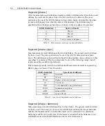
Page 54: ...ion may be specified without the phase portion keyword type in this case phase A is assumed The type portion may be any of the following strings not all results use all the available type formats This format is generally used when a full bandwidth measurement result is required e g RMS Voltage or Current Total Power etc ASCII characters Type of result defined RMS True RMS DC DC only PEAK Highest v...

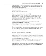
Page 55: ...nics are to be excluded from the evaluation of the result typically this would be the fundamental e g VOLTS 2 40 yields the total distortion voltage While all results are correctly evaluated as defined by the users harmonic range this may not always be the result intended e g K factor should not exclude the fundamental The phase portion is as described previously Keyword phase harmonic harmonic Th...

Page 56: ...hases AMPS phase PEAK The highest absolute peak measured instantaneous current amplitude The result format is floating point in Amps and is always positive TOTAL data is derived from the highest phase peak AMPS phase RMS The RMS current amplitude measurement result including DC if configured see the AC ONLY command over the full configured bandwidth see the BANDWIDTH command including any non harm...

Page 57: ...current amplitude The result format is floating point in Amps and is always positive TOTAL data is derived from the highest phase value A INRUSH phase RMS The highest inrush RMS current amplitude measurement result including DC if configured see the AC ONLY command over the full configured bandwidth see the BANDWIDTH command including any non harmonic content The result format is floating point in...

Page 58: ...ivisible by 3 with an even result e g 6 12 18 etc The result format is floating point in Amps and is always positive TOTAL is invalid for this result definition K FACTOR phase harmonic harmonic The current K factor measurement result evaluated for a range of harmonics The result format is floating point unitless and is always positive Note that the harmonic range should always include the fundamen...

Page 59: ...n for all phases VOLTS phase PEAK The highest modulus peak measured instantaneous voltage amplitude The result format is floating point in Volts and is always positive TOTAL data is derived from the highest phase value VOLTS phase RMS The RMS voltage amplitude measurement result including DC if configured see the AC ONLY command over the full configured bandwidth see the BANDWIDTH command includin...

Page 60: ...plitude The result format is floating point in Volts and is always positive TOTAL data is derived from the highest phase value V INRUSH phase RMS The highest inrush RMS voltage amplitude measurement result including DC if configured see the AC ONLY command over the full configured bandwidth see the BANDWIDTH command including any non harmonic content The result format is floating point in Volts an...

Page 61: ...uated for the fundamental component only The result format is floating point unitless PF phase RMS The power factor measurement result including DC if configured see the AC ONLY command over the full configured bandwidth see the BANDWIDTH command including any non harmonic content The result format is floating point unitless PF phase harmonic The power factor measurement result evaluated at the sp...

Page 62: ...armonic harmonic The real power measurement result evaluated for a range of harmonics The result format is floating point in VA and is always positive VAR phase FUND The imaginary power measurement result evaluated for the fundamental component only The result format is floating point in VAR VAR phase RMS The imaginary power measurement result including DC if configured see the AC ONLY command ove...

Page 63: ...lt format is floating point in Watts WATTS phase FUND The real power measurement result evaluated for the fundamental component only The result format is floating point in Watts WATTS phase RMS The real power measurement result including DC if configured see the AC ONLY command over the full configured bandwidth see the BANDWIDTH command including any non harmonic content The result format is floa...

Page 64: ...rox 5 full scale for the option fitted or that the frequency lies outside of the configured bandwidth See the BANDWIDTH command Defining Integrated Measurement Results A HR phase DC The integrated mean amplitude of the current input signal If configured as AC only then this result is always zero See the AC ONLY command The result format is floating point in Amp Hours TOTAL is invalid for this data...

Page 65: ...g only the DC components If configured as AC only then this result is always zero See the AC ONLY command The result format is floating point in VA Hours and is always positive VA HR phase RMS The integrated apparent power measurement result including DC if configured see the AC ONLY command over the full configured bandwidth see the BANDWIDTH command including any non harmonic content The result ...

Page 66: ...ase RMS The integrated RMS voltage amplitude measurement result including DC if configured see the AC ONLY command over the full configured bandwidth see the BANDWIDTH command including any non harmonic content The result format is floating point in Volt Hours and is always positive TOTAL is invalid for this data V INTEG AVG phase DC The average integrated mean amplitude of the voltage input signa...

Page 67: ...ny non harmonic content The result format is floating point in Watts Defining Waveform Results With the exceptions noted each of these returns a set of 200 results The first result is that at 0 phase of the phase A voltage waveform each successive result being at pi 100 radians increased delay from the previous A WAVEFORM phase The set of current waveform amplitudes building the actual current wav...

Page 68: ...he set of evaluated current distortion results that have been stored historically Each result is floating point in percent relative to fundamental and is always positive Note that this yields 1600 characters in total TOTAL is the mean value for all phases HISTORY DATE The set of dates which correspond to each measurement result that has been stored historically Results that have not been placed in...

Page 69: ...g point in VAR Note that this yields 1600 characters in total V HISTORY phase PEAK The set of highest instantaneous absolute voltage amplitudes that have been stored historically Each result is floating point in Volts and is always positive Note that this yields 1600 characters in total TOTAL is the highest value for all phases V HISTORY phase RMS The set of RMS voltage amplitudes that have been s...

Page 70: ...ative results DATE The present date is formatted as an ASCII string mmm dd yyyy mmm is the three letter month dd is the numeric date yyyy is the four digit year TIME The time of day is formatted as an ASCII string hh mm ss hh is the two digit hour of the day mm is the minute ss is the second ...

Page 71: ...53 2553E Simple Interfacing For many applications the interfacing of the 2553 2553E follows the example given below The user should check whether a different configuration is required the default configuration is used in this example and whether different measurement results are required 1 Send the IEEE488 1 interface DCL Device Clear command This ensures that the 2553 2553E IEEE488 1 physical int...

Page 72: ...h other devices are operated cannot be covered here but the general outline of their interface will normally integrate with the outline shown below Placing the 2553 2553E into a Known State Whenever the controller is first activated with the 2553 2553E attached to it via the IEEE488 interface it is important that the user have knowledge of its state such that all operations will yield the desired ...

Page 73: ...rmware in the 2553 2553E This is of particular importance if a future version adds a new feature that is not currently available If the user software is reliant on this new feature then it is important that the version of 2553 2553E firmware is checked for compatibility This can be checked by sending the any of the following interrogative commands and reading the responses to them from the 2553 25...

Page 74: ...measurement results e g Watt Hours etc this command may be used in other places in this sequence if exact timing is required AVERAGE If measurement results are to be averaged over a period other than 250ms BANDWIDTH If measurements are to be made over a bandwidth of other than 20Hz to 5KHz AC ONLY If measurements are to be made without the inclusion of any DC signal content SYNC If the measurement...

Page 75: ...uired from the 2553 2553E and possibly which data will be required from which bank then the user should program the respective banks using the BANK0 BANK1 BANK2 BANK3 and BANK4 commands To ensure that an unused bank does not contain a definition which would take the 2553 2553E time to format it is recommended that unused banks be cleared by sending the respective BANKn command with no character an...

Page 76: ...lication by parsing the data into an array and then plotting the array or the actual response may be written as a file and the file imported at a later date into a spreadsheet program for analysis or plotting When bank 2 is read the number of valid data points comma delimited followed by a 200 point comma delimited set of RMS Voltage historical results followed by a 200 point comma delimited set o...

Page 77: ...command The user need not be concerned with maintaining synchronism with the 2553 2553E or be concerned about the 2553 2553E forcing the controller to wait for new measurement results as they are always available to be read Since the default after application of power is to use bank 0 this should be the bank chosen The UPDATE and READBANK commands need not be used Asynchronously Reading Measuremen...

Page 78: ...the controller sends the STATUS NL interrogative command to the 2553 2553E and then reads the present SRQ Response Byte Status The application then converts the returned integer into binary and checks if bit 2 is set See Table 1 page 16 If bit 2 is set then the controller reads the 2553 2553E again this time the contents of bank 0 will be returned because the response to the interrogative has been...

Page 79: ...umentation for the particular controller and software being used Some packages automatically perform the serial poll Changing the Configuration of the 2553 2553E In rare circumstances it may be required to reconfigure measurements in the 2553 2553E after the initial configuration that was performed when the application was started Following any change to the measurement configuration of the 2553 2...

Page 80: ...updated at the fastest possible rate virtually in real time Full Bandwidth Amplitude Measurements RMS DC and similar measurements follow the time scales discussed previously It is often advantageous to synchronize using the MEASURE command if these measurement results are desired at the fastest possible rate There is some improvement in speed if the user maintains the voltage signal to the 2553 25...

Page 81: ...story file The user should check that the controller and software can accommodate any requirements on this with particular regard to any other activities which the controller may be performing Commanding the 2553 2553E to Produce Printouts It is often advantageous to program the controller to command the 2553 2553E to perform printouts This ensures that the correct printouts are obtained in a cons...

Page 82: ...ted in this guide The method of performing this using National Instruments LabView is available on request the user should contact Vitrek for assistance in this regard if required Debugging the Application When debugging IEEE488 control applications the following points should be considered Initially send all commands as single commands i e do not send multiple commands with a single terminator In...

Page 83: ...he same address 3 Check if there are multiple applications using the same IEEE488 controller In some circumstances and under some operating systems this cannot be performed due to controller or software limitations 4 Attempt to communicate with i e send commands to the 2553 2553E Use a simple command like MEASURE STOP Under some circumstances when the 2553 2553E is first plugged into the IEEE488 c...

Page 84: ... situation arises if the device enters the LOCAL state when it was previously addressed to listen and no other bus address has been used since that time this could have been days or even weeks ago The controller will not place the 2553 2553E or other device back into REMOTE because it will not re address it when configured in the LOCAL state In this case any data apparently sent to the 2553 2553E ...

Page 85: ... that you are using for details regarding how to do this 4 The front panel displayed COMMAND ERROR when the commands noted in 1 or 2 were transmitted If this was the case then the 2553 2553E ignored the command The user should check the syntax of the command carefully 5 The commands noted in 1 and 2 were sent to the correct address 6 A device clear RST or CLS command was not sent to the 2553 2553E...

Page 86: ...use of the most significant bit as a parity bit Although the 2553 2553E only uses the 7 bit ASCII command set it does check the entire set of 8 bits of the IEEE488 data bus Check if the use of the most significant bit for parity can be disabled After a READBANK or BANKn command how long do I have to delay before the new data is available The 2553 2553E automatically switches to the new bank or res...

Page 87: ...L is sent to the 2553 2553E 3 The 2553 2553E is read The data indicates that the AVERAGE setting is 1 I want to calibrate my 2553 2553E using the IEEE488 bus but I cannot find the commands to do so How do I do this Calibration is dependent on the option content of the 2553 2553E product All 2553 2553E units require specialized calibration equipment that can if misused seriously affect the performa...

Page 88: ... are the following listed in order of importance with the most significant first 1 Using a high speed controller which has been correctly configured The 2553 2553E is capable of operating with handshake delays down to 350ns the default configuration for many controllers is set to either 500ns common or even 1µs older controllers If there are no open collector type bus devices on the IEEE488 bus th...

Page 89: ...uld contact National Instruments regarding upgrading the isolator Other isolators and controllers may also have this problem Many IEEE488 bus instruments only format a response when addressed to talk thus there is usually some delay between the device being addressed to talk and the device starting to place data onto the bus The 2553 2553E always has pre formatted responses available thus there is...

Page 90: ...h speed common mode interference on the measurement signals will cause common mode interference on the chassis of the 2553 2553E Grounding significantly reduces this If necessary use the rear panel chassis ground binding post to securely ground the chassis use heavy gauge wire or braid for good high frequency grounding Check the maximum length of any IEEE488 cable and the overall maximum When usin...

Page 91: ...in them For all voltage and current peak results the TOTAL is the highest for any configured phase For all voltage and current RMS and DC results the TOTAL is the mean for all configured phases For voltage and current crest factor results the TOTAL is calculated from the TOTAL peak and RMS results described above For all voltage and current harmonic amplitude results the TOTAL is the mean for all ...

Page 92: ...e phase shift between the voltage phases in a multi phase configuration Since all harmonic phase results both voltage and current are relative to phase A voltage signal the fundamental phase for phases B and C yield the phase shift between the phases ...

Page 93: ... 2553E option content RST Power reset the 2553 2553E SRE Interrogates the enabled causes of 2553 2553E SRQ activity STB Interrogates the 2553 2553E serial poll response byte AC ONLY Interrogates the setting for the AC ONLY command AC ONLY data Sets measurement results to be AC only or AC and DC AVERAGE Interrogates the setting for the AVERAGE command AVERAGE data Sets the measurement result averag...

Page 94: ...ing for the MEASURE command MEASURE data Enables or disables update of all measurement results PRINT data Selects and initiates a printout PRINT STATUS Interrogates the status of the parallel printer port PRODUCT Interrogates the product and option content READBANK data Sets the transmit buffer bank to be used SET DC ZERO Sets the DC current input offset SETDEFAULTS Sets the 2553 2553E to a defaul...

Page 95: ...alued absolute peak RMS True RMS THD of fundamental using all harmonics WORST Same as PEAK The phase portion may be A B C or TOTAL TOTAL is not available for all result definitions The summary of the result definitions is listed in alphabetical order A HISTORY phase type Historical current results A HR phase type Integrated current A INRUSH phase type Inrush current A INTEG AVG phase type Integrat...

Page 96: ...e TRIPLENS phase harmonic harmonic Triplens current VA phase type VA phase harmonic VA phase harmonic harmonic VA phase harmonic harmonic Apparent Power VA VA HR phase type Integrated apparent power VA VA INTEG AVG phase type Integrated average apparent power VA VAR phase type VAR phase harmonic VAR phase harmonic harmonic VAR phase harmonic harmonic Imaginary Power VAR VAR HISTORY phase Historica...

Page 97: ...oltage percentage of fundamental V WAVEFORM phase Voltage waveform WATTS phase type WATTS phase harmonic WATTS phase harmonic harmonic WATTS phase harmonic harmonic Real Power Watts W HISTORY phase Historical real power results W HR phase type Integrated real power Watts W INRUSH phase type Inrush real power Watts W INTEG AVG phase type Integrated average real power Watts W WAVEFORM phase Power wa...

Reviews: