Sending Commands and Interrogatives 109
USB
The user should read the reply to an interrogative from the “interrogative”
response linkage to the driver DLL. See the driver DLL documentation for
details regarding this.
RS232
The 2801/2 automatically transmits the response over the RS232
Note: For RS232 after sending the READ = command, you must send the
character “ ? ” to the unit or you will not get a reply
IEEE488
Any interrogative responses become the highest priority data for the next read
of the 2801/2 which the user performs. If the user sends another command
without reading any pending interrogative responses, then they are discarded.
Once the user has read any pending interrogative response, then the 2801/2
will revert to sending the measurement result response data when next read
via the IEEE488 interface.
Remote / Local Operation
Any interface can command that the front panel user be locked out from
making changes. This does not lock out the user from viewing menus, it only
locks out the user from making changes within them. When any command is
received over any interface any menu open by the front panel user will be
closed.
If any interface has commanded remote, then the first level menu (accessed by
the MENU key) has an entry on the first line entitled RETURN TO LOCAL
MODE. If the front panel user highlights this entry and presses ENTER then
all interfaces will be returned to the LOCAL state if they are able.
Any interface can command the instrument at any time, whether in the local
or remote state.
To command the remote or local state via any interface the REMOTE
command is used.
REMOTE=0 – places the unit in the local state.
REMOTE=1 – places the unit in the remote state.
Summary of Contents for Xitron 2801
Page 1: ...USER GUIDE 2801 2802 Advanced Single and Dual Channel Power Analyzers...
Page 2: ...2 2801 2802 Power Analyzer User Guide...
Page 10: ...10 2801 2802 Power Analyzer User Guide...
Page 101: ...Printing Results 101 Figure 66 Configuration Printout...
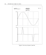
Page 102: ...102 2801 2802 Power Analyzer User Guide Figure 67 Waveform Channel 1 Real time...
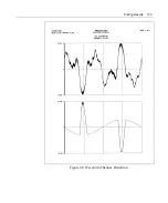
Page 103: ...Printing Results 103 Figure 68 Waveform Channe1 Distortion...
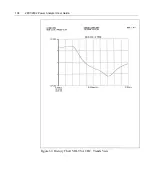
Page 104: ...104 2801 2802 Power Analyzer User Guide Figure 69 History Chart VOLTS ACDC Trends View...
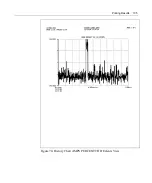
Page 105: ...Printing Results 105 Figure 70 History Chart AMPS PERCENT THD Extents View...
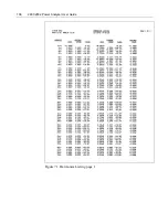
Page 106: ...106 2801 2802 Power Analyzer User Guide Figure 71 Harmonics Listing page 1...
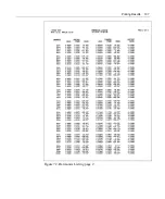
Page 107: ...Printing Results 107 Figure 72 Harmonics Listing page 2...
Page 145: ...Sending Commands and Interrogatives 145...
Page 147: ...Appendix A Physical Specifications 147...


