Introduction 11
Figures
Figure 1. Overall Block Diagram ____________________________________ 17
Figure 2. Voltage Input Attenuator Block Diagram_______________________ 19
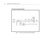
Figure 3. Transducer Input Attenuator Block Diagram____________________ 20
Figure 4. Current and Line Switch Block Diagram _______________________ 21
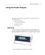
Figure 5. Benchtop Version of 2801 Power Analyzer ____________________ 25
Figure 6. Benchtop Version of 2802 Power Analyzer ____________________ 26
Figure 7. 2801 Front Panel Interface Detail ____________________________ 27
Figure 8. 2802 Front Panel Interface Detail ____________________________ 27
Figure 9. Sample Display __________________________________________ 27
Figure 10. Rear Connection Panel___________________________________ 33
Figure 11. Measuring a Power Source, Method 1 _______________________ 34
Figure 12. Measuring a Power Source, Method 2 _______________________ 35
Figure 13. Measuring a Load, Method 1 ______________________________ 36
Figure 14. Measuring a Load, Method 2 ______________________________ 37
Figure 15. Measuring a Source Using a CT, Method 1 ___________________ 38
Figure 16. Rear Connection Panel___________________________________ 39
Figure 17. Measuring a Power Source, Method 1 _______________________ 40
Figure 18. Measuring a Power Source, Method 2 _______________________ 41
Figure 19. Measuring a Load, Method 1 ______________________________ 42
Figure 20. Measuring a Load, Method 2 ______________________________ 43
Figure 21. Measuring a Power Source and Load, Method 1, Two Ind. Chnls __ 44
Figure 22. Measure 3P-3W 2 Meter Connection, Method 1 _______________ 45
Figure 23. Measuring a Source Using a CT, Method 1 ___________________ 47
Figure 24. External Transducer Test Connections ______________________ 48
Figure 25. Startup Screen 2801 and 2802 _____________________________ 50
Summary of Contents for Xitron 2801
Page 1: ...USER GUIDE 2801 2802 Advanced Single and Dual Channel Power Analyzers...
Page 2: ...2 2801 2802 Power Analyzer User Guide...
Page 10: ...10 2801 2802 Power Analyzer User Guide...
Page 101: ...Printing Results 101 Figure 66 Configuration Printout...
Page 102: ...102 2801 2802 Power Analyzer User Guide Figure 67 Waveform Channel 1 Real time...
Page 103: ...Printing Results 103 Figure 68 Waveform Channe1 Distortion...
Page 104: ...104 2801 2802 Power Analyzer User Guide Figure 69 History Chart VOLTS ACDC Trends View...
Page 105: ...Printing Results 105 Figure 70 History Chart AMPS PERCENT THD Extents View...
Page 106: ...106 2801 2802 Power Analyzer User Guide Figure 71 Harmonics Listing page 1...
Page 107: ...Printing Results 107 Figure 72 Harmonics Listing page 2...
Page 145: ...Sending Commands and Interrogatives 145...
Page 147: ...Appendix A Physical Specifications 147...


