18
2801/2802 Power Analyzer User Guide
Analog Channel Board
The 2801 is built with one and the 2802 is built with two Analog Channel
Boards fitted. The block diagrams of this circuitry are shown below.
Voltage Input Attenuator Notes
The primary voltage-reducing element formed by the 1 Mohm portion of the
attenuator is comprised of several lesser value resistors in series:
a) To assure the input remains safe when a single resistor fails to a short
circuit;
b) To reduce the voltage coefficient of the attenuator caused by self heating
when high voltages are applied; and
c) To ensure that the input can withstand high voltages in excess of the
maximum specified to the user.
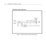
Transducer Input Attenuator Notes
The Transducer input attenuator is similar to the Voltage input attenuator but
with a much lower primary resistance value and a slightly higher output
impedance. Since the input voltages specified are low, only a single primary
attenuator resistor is used as there are no single fault safety issues with this
input.
Summary of Contents for Xitron 2801
Page 1: ...USER GUIDE 2801 2802 Advanced Single and Dual Channel Power Analyzers...
Page 2: ...2 2801 2802 Power Analyzer User Guide...
Page 10: ...10 2801 2802 Power Analyzer User Guide...
Page 101: ...Printing Results 101 Figure 66 Configuration Printout...
Page 102: ...102 2801 2802 Power Analyzer User Guide Figure 67 Waveform Channel 1 Real time...
Page 103: ...Printing Results 103 Figure 68 Waveform Channe1 Distortion...
Page 104: ...104 2801 2802 Power Analyzer User Guide Figure 69 History Chart VOLTS ACDC Trends View...
Page 105: ...Printing Results 105 Figure 70 History Chart AMPS PERCENT THD Extents View...
Page 106: ...106 2801 2802 Power Analyzer User Guide Figure 71 Harmonics Listing page 1...
Page 107: ...Printing Results 107 Figure 72 Harmonics Listing page 2...
Page 145: ...Sending Commands and Interrogatives 145...
Page 147: ...Appendix A Physical Specifications 147...


