Using the Power Analyzer
29
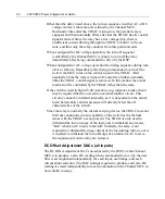
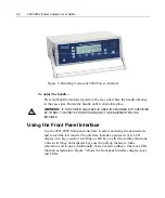
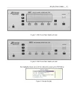
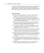
The LEDs designated OVERLOAD V and A indicate the
selected current/voltage threshold has been exceeded, such
as, an input signal is greater than the selected range value,
above strict ranging or the selected maximum range. Note
that when either of these LEDs remains lighted, changes to
the test device’s signal input or values in the SETUP
MEASUREMENTS MENU are required.
2802 is shown, 2801 only has CH1 Overload LEDs
A lighted LED at LINE ON/OFF indicates that power has
been turned on to the device connected to the analyzer for
testing/measuring.
Hold the LINE ON/OFF key for a few milliseconds to
power up or power down the test device. Note that this line
switch is ENABLED or DISABLED from within the
SETUP MEASUREMENTS MENU.
The PRINT key allows the user to print a full page of data
reflecting the display results. The formatting of the printout
is either graphical or numerical tabulation.
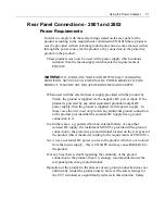
The F1, F2, F3 and F4 keys are softkeys. They correlate
with labels given on the display. The softkey labels indicate
other options available or the status of the display. An
ellipsis (…) following the label indicates additional choices
available. See below.
OVERLOAD
CH 1
V
A
CH 2
LINE
ON / OFF
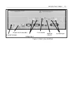
Grounding of the Analyzer
There are two distinct grounded areas built into the 2801/2802 Power
Analyzer.
Chassis Ground
This comprises the entire external and internal chassis mechanical
components, the outside shells of all interface connectors, and the shield
connection in the IEEE488 interface connector. An external protective
ground terminal is directly connected to this ground.
Internal Electronic Ground
This comprises all grounded circuitry within the product and is the reference
Summary of Contents for Xitron 2801
Page 1: ...USER GUIDE 2801 2802 Advanced Single and Dual Channel Power Analyzers...
Page 2: ...2 2801 2802 Power Analyzer User Guide...
Page 10: ...10 2801 2802 Power Analyzer User Guide...
Page 101: ...Printing Results 101 Figure 66 Configuration Printout...
Page 102: ...102 2801 2802 Power Analyzer User Guide Figure 67 Waveform Channel 1 Real time...
Page 103: ...Printing Results 103 Figure 68 Waveform Channe1 Distortion...
Page 104: ...104 2801 2802 Power Analyzer User Guide Figure 69 History Chart VOLTS ACDC Trends View...
Page 105: ...Printing Results 105 Figure 70 History Chart AMPS PERCENT THD Extents View...
Page 106: ...106 2801 2802 Power Analyzer User Guide Figure 71 Harmonics Listing page 1...
Page 107: ...Printing Results 107 Figure 72 Harmonics Listing page 2...
Page 145: ...Sending Commands and Interrogatives 145...
Page 147: ...Appendix A Physical Specifications 147...

