34
2801/2802 Power Analyzer User Guide
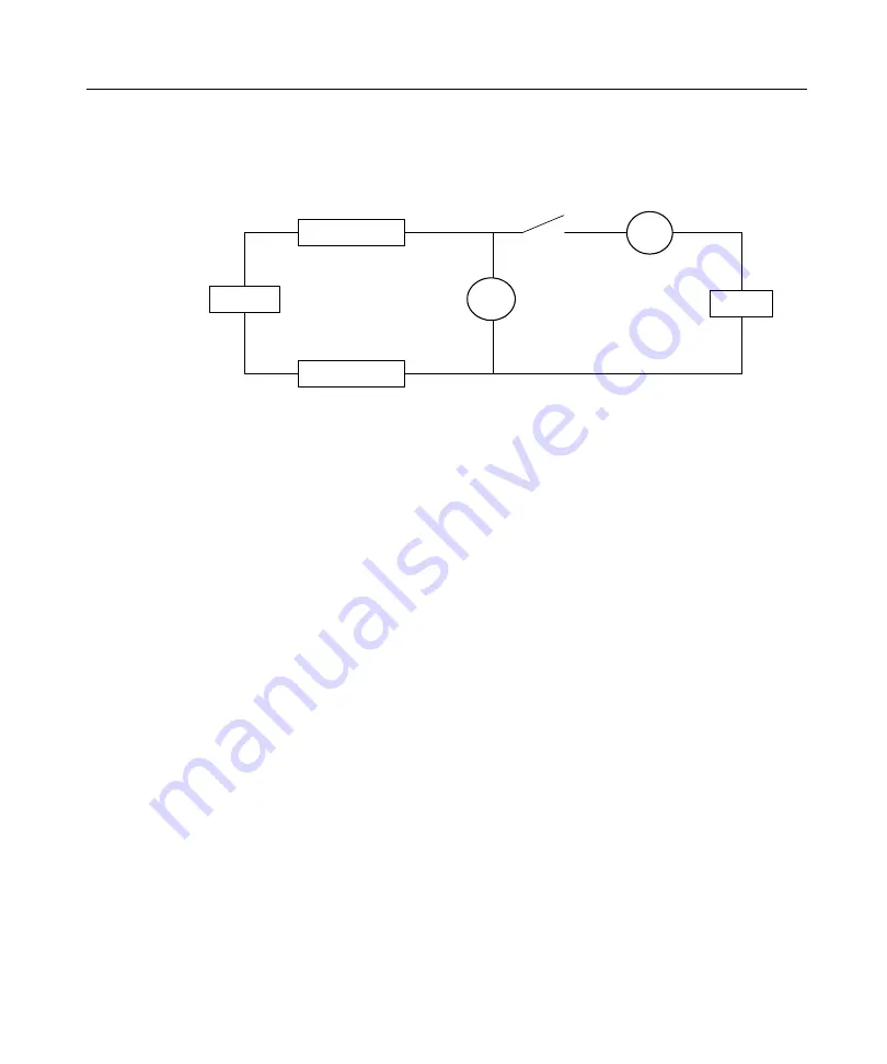
Single-Channel Measurements of a Power Source:
Connection Method 1
Wiring Loss
Wiring Loss
V
A
Source
Load
+
-
+
-
Optional
Line Switch
W
1
ohms
W
2
ohms
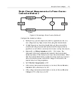
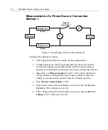
Figure 11. Measuring a Power Source, Method 1
Configure the channel as follows -
•
This connection method is suitable for most applications.
•
At high frequencies, the wiring length between the source and the
current and voltage measurement points should be kept as short as
possible to avoid inductive and capacitive losses causing inaccuracies.
•
Optionally, set
Wiring Impedance
to (W1 + W2) ohms. Include all
wiring resistances between the source and the points at which the
voltage is measured in the entered value for wiring impedance.
•
Set
V Burden Compensation
to YES.
•
If the current measurement terminals are reversed, then set
Reverse
Current
to
YES
, otherwise set to
NO
.
•
If the voltage measurement terminals are reversed, then set
Reverse
Voltage
to
YES
, otherwise set to
NO
.
Summary of Contents for Xitron 2801
Page 1: ...USER GUIDE 2801 2802 Advanced Single and Dual Channel Power Analyzers...
Page 2: ...2 2801 2802 Power Analyzer User Guide...
Page 10: ...10 2801 2802 Power Analyzer User Guide...
Page 101: ...Printing Results 101 Figure 66 Configuration Printout...
Page 102: ...102 2801 2802 Power Analyzer User Guide Figure 67 Waveform Channel 1 Real time...
Page 103: ...Printing Results 103 Figure 68 Waveform Channe1 Distortion...
Page 104: ...104 2801 2802 Power Analyzer User Guide Figure 69 History Chart VOLTS ACDC Trends View...
Page 105: ...Printing Results 105 Figure 70 History Chart AMPS PERCENT THD Extents View...
Page 106: ...106 2801 2802 Power Analyzer User Guide Figure 71 Harmonics Listing page 1...
Page 107: ...Printing Results 107 Figure 72 Harmonics Listing page 2...
Page 145: ...Sending Commands and Interrogatives 145...
Page 147: ...Appendix A Physical Specifications 147...

