46
2801/2802 Power Analyzer User Guide
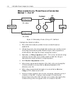
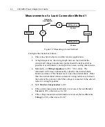
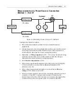
The above diagram is applicable when there are 3 wires connecting to the
Load. For ease, we have used X, Y and Z instead of A, B and C. The phase
rotation of the Channels must be opposite of each other and the current
measurement is made in the line phase connected to the corresponding voltage
HI terminal.
Configure the channels as follows -
•
Select 3P-3W from the Getting Started Menu.
•
The 2802 will provide the following results
Two of the actual measured voltages (X-Z and Y-Z)
The Voltage Difference (= Y-X)
Two of the actual measured currents (X and Y)
The Sum Current (=Z)
The individual and totals for VA, W, VAR, PF etc.
•
If the current measurement terminals are reversed, then set
Reverse
Current
to
YES
, otherwise set to
NO
. (Only if both currents are
backwards)
•
If the voltage measurement terminals are reversed, then set
Reverse
Voltage
to
YES
, otherwise set to
NO
. .(Only if both Voltages are
backwards)
Summary of Contents for Xitron 2801
Page 1: ...USER GUIDE 2801 2802 Advanced Single and Dual Channel Power Analyzers...
Page 2: ...2 2801 2802 Power Analyzer User Guide...
Page 10: ...10 2801 2802 Power Analyzer User Guide...
Page 101: ...Printing Results 101 Figure 66 Configuration Printout...
Page 102: ...102 2801 2802 Power Analyzer User Guide Figure 67 Waveform Channel 1 Real time...
Page 103: ...Printing Results 103 Figure 68 Waveform Channe1 Distortion...
Page 104: ...104 2801 2802 Power Analyzer User Guide Figure 69 History Chart VOLTS ACDC Trends View...
Page 105: ...Printing Results 105 Figure 70 History Chart AMPS PERCENT THD Extents View...
Page 106: ...106 2801 2802 Power Analyzer User Guide Figure 71 Harmonics Listing page 1...
Page 107: ...Printing Results 107 Figure 72 Harmonics Listing page 2...
Page 145: ...Sending Commands and Interrogatives 145...
Page 147: ...Appendix A Physical Specifications 147...

