Using the Power Analyzer
39
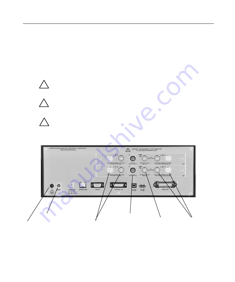
2802 Rear Panel Connections
!
!
!
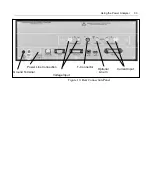
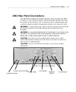
The 2802 Power Analyzer rear panel contains a variety of connectors. Refer
to Figure 16. The connectors used for testing/measuring functions are along
the midline of the instrument. The connectors used for communications and
control are along the bottom. The ground terminal is at the lower left corner.
WARNING:
IF THE POWER ANALYZER IS USED IN A MANNER NOT SPECIFIED
BY
VITREK
, THE PROTECTION PROVIDED BY THE EQUIPMENT MAY BE
IMPAIRED.
WARNING:
IT IS RECOMMENDED THAT THE PROTECTIVE CONDUCTOR
TERMINAL IS CONNECTED TO EARTH GROUND WHEN THE SIGNALS
BEING MEASURED ARE REFERENCED TO EARTH GROUND.
CAUTION:
THE USE OF THE T5 CHARGER FROM
VITREK
OR A
VITREK
RECOMMENDED REPLACEMENT MUST BE USED TO ENSURE THAT THE UNIT
GROUND IS NOT COMPROMISED
.
CAUTION:
FOR ALL CONNECTIONS, KEEP INPUT AND OUTPUT WIRING
SEPARATED.
Figure 16. Rear Connection Panel
Power Line Connection
Current Input
T- Connector
Optional
Line In
Voltage Input
Ground Terminal
Summary of Contents for Xitron 2801
Page 1: ...USER GUIDE 2801 2802 Advanced Single and Dual Channel Power Analyzers...
Page 2: ...2 2801 2802 Power Analyzer User Guide...
Page 10: ...10 2801 2802 Power Analyzer User Guide...
Page 101: ...Printing Results 101 Figure 66 Configuration Printout...
Page 102: ...102 2801 2802 Power Analyzer User Guide Figure 67 Waveform Channel 1 Real time...
Page 103: ...Printing Results 103 Figure 68 Waveform Channe1 Distortion...
Page 104: ...104 2801 2802 Power Analyzer User Guide Figure 69 History Chart VOLTS ACDC Trends View...
Page 105: ...Printing Results 105 Figure 70 History Chart AMPS PERCENT THD Extents View...
Page 106: ...106 2801 2802 Power Analyzer User Guide Figure 71 Harmonics Listing page 1...
Page 107: ...Printing Results 107 Figure 72 Harmonics Listing page 2...
Page 145: ...Sending Commands and Interrogatives 145...
Page 147: ...Appendix A Physical Specifications 147...

