background image


Front Panel Operation 

23 


The 

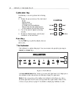
NULLMETER SCALE 

key allows you to select the: 

• 

Scaling type: dot or bar; 

• 

Linearity: linear or logarithmic; 

• 

Zero position: left, centered, or mirrored around the center.  

Note: 

The center zero position, log-scaled format provides a useful adjustment 

capability of “coarse/medium/fine”. Refer to 

Nullmeter Scale Menu

 on page 58, 

for more details. 

Input Connector Keys & Indicators 

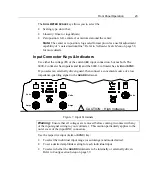
Use either the voltage (

V

) or the current (

A

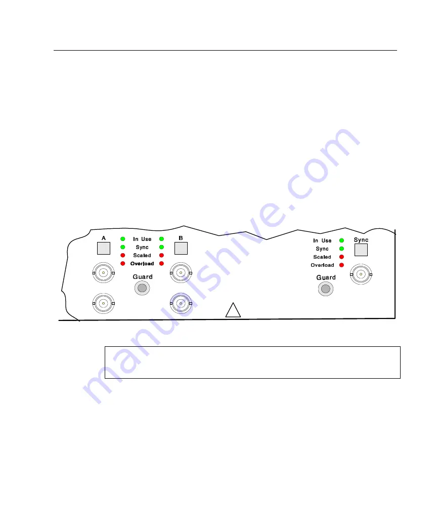
) input connection, but not both. The 

6000-2 voltmeter has inputs 

A

 and 

B

, and the 6000-3 voltmeter has 

A

B

 and 

SYNC

.  

If you select an externally driven guard, then connect a convenient source of a low 
impedance-guarding signal to the 

GUARD

 terminal.  

Volts

Amps

Amps

Volts

Volts

CAUTION :  High Voltages

!


Figure 7. Input Terminals 

Warning:

  Ensure that all voltages are removed before coming in contact with any 

of the input signal wiring to your voltmeter.  This caution particularly applies to the 
outer cover of the input BNC connectors.  

Use the respective input (

A

B

, or 

SYNC

) key: 

• 

To select the individual input range (or autorange) and mode desired. 

• 

To set a desired amplitude scaling for each individual input. 

• 

To select whether the 

GUARD 

terminal is to be internally or externally driven.  

Refer to 

Configuration Setup

 on page 39. 

Summary of Contents for Xitron 6000-2

Page 1: ...USER S GUIDE 6000 2 6000 3 Phase Angle Voltmeters...

Page 2: ......

Page 3: ...ive as a result of misuse improper repair or abnormal conditions or operations repairs will be billed at cost Vitrek assumes no responsibility for its product being used in a hazardous or dangerous ma...

Page 4: ...ch is subject to change without notice The product displays and manual text may be used or copied only in accordance with the terms of the license agreement is a trademark of Vitrek All other trademar...

Page 5: ..._________________________ 17 Front Panel Operational Features______________________________17 Power Switch __________________________________________ 17 The Display ___________________________________...

Page 6: ...____________________________ 38 RS232 Connectors ______________________________________ 38 IEEE488 Connector _____________________________________ 38 Configuration Setup_______________________________...

Page 7: ...88 Interface Setup ____________________________________64 Configuring the Controller Card ___________________________ 65 Configuring the Controller Software ________________________ 66 Interrogating t...

Page 8: ...________ 91 Calibration Procedure____________________________________ 91 Performing a Partial Calibration ______________________________93 Performing a Calibration Check Only _________________________...

Page 9: ...Examples To change a display line of Results Data _______________________________ 26 To select an option ________________________________________________ 26 To set defaults ___________________________...

Page 10: ...ut connector _________________________ 41 To change the input scale factor ____________________________________ 42 Setting the Guard connection for each input connector ____________________ 42 To conf...

Page 11: ...tectors or other delicate inaccurate circuitry These instruments have a 0 0005Hz to 200kHz range of frequencies True 18 bit resolution on each input which yields exceptional phase amplitude and harmon...

Page 12: ...s fitted Principles of Operation For basic details regarding the circuitry and methods used in the 6000 instruments Figure 1 shows the overall block description of their internal system s circuitry Ce...

Page 13: ...this processor is stored in flash memory allowing the instrument s software to be field upgradeable without requiring removal of the covers or any circuitry The interface of this processor to the inte...

Page 14: ...he same nominal phase shift independent of gain setting Each input system also presents the GUARD terminal connection to its amplitude and supervisory DSPs to act as the common for their isolated powe...

Page 15: ...an underload condition remains for longer than a period provided by the central processor actually set by the minimum fundamental frequency expected then the DSP changes the range presented to the in...

Page 16: ...y up to 1 however the average over any 256 sample period is always within 1ppm of the set value This jittered sampling ensures that no input signal component can be synchronous to the amplitude system...

Page 17: ...the menus Front Panel Operational Features The 6000 2 and 3 Phase Angle Voltmeter instruments have a number of controls and indicators available See Figure 4 Figure 4 The 6000 3 Voltmeter Front Panel...

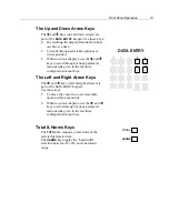
Page 18: ...bed below To place a cursor in a display line use a DISPLAY SELECT key which are the corresponding unmarked keys on the right Press the ENTER key once to remove the cursor Press it twice to action the...

Page 19: ...in the last three configuration menu lines The Left and Right Arrow Keys The and keys left and right arrows are part of the DATA ENTRY keypad Use these keys To move the cursor to a new selectable opt...

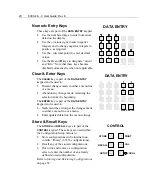
Page 20: ...er a menu line or a menu Abandon any change made restarting the selection from the beginning The ENTER key is part of the DATA ENTRY keypad and is used to Implement the action per the changes made in...

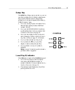
Page 21: ...set the display format of time and date information Refer to Setting Format ting Time Date on page 31 for details Use to set the internal real time clock Use to enable the key to scroll the display to...

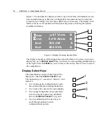
Page 22: ...INT key to print the display menu or data results SETUP RECALL STORE CONTROL PRINT CAL LOCAL The Nullmeter The nullmeter is a lighted bargraph You can customize the graph by pressing its SELECT and SC...

Page 23: ...eter has A B and SYNC If you select an externally driven guard then connect a convenient source of a low impedance guarding signal to the GUARD terminal Volts Amps Amps Volts Volts CAUTION High Voltag...

Page 24: ...measuring amplitudes and or distortion of a single signal use input A If measuring phase or phase related amplitudes between a pair of signals connect the reference signal to input A and the unknown s...

Page 25: ...tages reduce potential interference and crosstalk between inputs by the use of shielded cables e g coaxial cable If input capacitance is of concern then use tightly wound wires of small gage twisted p...

Page 26: ...in the display line to allow you to Directly change the displayed information at the cursor Change the displayed selection to the next one available 3 Use the and keys to move the cursor to the data o...

Page 27: ...e default Parameter setup is p True RMSAh 1 1 Display as volts rms Filter 0 000S For line 01 the Results Data is Fund xx xu Vrms B The default Parameter setup is p True RMSBh 1 1 Display as volts rms...

Page 28: ...the cursor remains in the item being changed Or Select an all uppercase heading line and press the DISPLAY SELECT 1 key Press a new DISPLAY SELECT key To change a display line 1 Within the Results Dat...

Page 29: ...the cursor but rather than implementing the change allows you to make another edit 4 When the displayed menu has been changed to suit your requirements press the ENTER key once if no cursor is flashi...

Page 30: ...shes in a display line as a separator 1 Press the DISPLAY SELECT key next to the Results Data display line to have separation dashes below it The display will show details of the presently selected pa...

Page 31: ...lts Data Note The selected display changes apply when printing if the option INT is fitted To adjust the time display 1 Initiate this menu by pressing the SETUP key 2 Use the key to scroll to Set Time...

Page 32: ...press the DISPLAY SELECT key next to the Date Format display line 2 Use the key to toggle between the three choices of dd mm yy yy mm dd and mm dd yy Note that the displayed date is based on format 3...

Page 33: ...aintained even when the instrument is not powered up for 10 years To store a configuration in an already defined storage area 1 Press the STORE key 2 Use the or keys to scroll through the numerically...

Page 34: ...or recall another storage area To rename an existing storage area 1 Press either the STORE or RECALL key 2 Press the DISPLAY SELECT key next to the Edit Directory menu line 3 Scroll using the or keys...

Page 35: ...written storage area until the memory becomes full When full the system automatically retrieves all storage areas into internal volatile memory erases the entire non volatile memory and then rewrites...

Page 36: ...36 6000 2 3 User Guide Rev E...

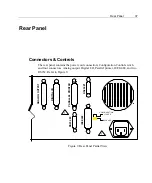
Page 37: ...cord connection Configuration Control switch and four connectors Analog output Digital I O Parallel printer IEEE 488 and two RS232 Refer to Figure 9 ANALOG OUTPUT DIGITAL I O PARALLEL PRINTER RS232 1...

Page 38: ...fined memory locations The following changes are made to the menus when in the Configuration Control switch is in the LOCKED position Display lines cannot be altered The SETUP and STORE keys are disab...

Page 39: ...ndard setup configure each input independently for input mode fundamental frequency ranging and scale factor Setup the input pair s GUARD terminal for internal or external connection Refer to the foll...

Page 40: ...re of the INPUTS keys A B AB or SYNC 3 only Those located above the BNC connectors Note that if the display reads an input such as A and you press A the display will read none You may get two differen...

Page 41: ...surements using DC coupling Update the display by pressing the DISPLAY SELECT 2 key twice and using the or keys to alter the option The input mode choices are V dc V ac V 50 and A dc Note Use the resp...

Page 42: ...nections Lo Input A Lo Input B or Lo Input Sync 3 only 3 When complete with your input connector selections press ENTER to action the changes To configure the Nullmeter parameter display The Nullmeter...

Page 43: ...lt scale factor of 1 0 shows in the display then no input scaling is performed You may enter any desired scale factor including negative factors for application to each input Negative scale factors ar...

Page 44: ...ndicated for the instrument s fundamental frequency Measured multiplied by a factor The option Meas x 000000 allows you to select an input measured frequency multiplied by a defined factor as its fund...

Page 45: ...fying a fundamental frequency range consider that the instrument will take the lowest frequency component having a signal of greater than 5 of range as its fundamental If there is signal having a sub...

Page 46: ...but the shortest of periods this effectively sets the results update rate of the instrument Note that the default measurement period is 250S The update rate of the display is limited to 250mS and the...

Page 47: ...s reduced in accordance with the ratio Maximum Harmonics This sets the Maximum Harmonic number that will be available for Results Data The display reads Max Harmonics The default is 200 Setting a high...

Page 48: ...is 4096 Maximum Harmonic Setting the RBW ratio to a high value may result in instability of measurement results particularly at higher harmonics Note If a value of 100 is set for RBW then the frequenc...

Page 49: ...ASUREMENT PERIOD menu line sets the base measurement period for the fundamental frequency measurement Setting this measurement to a longer period than the default of 250mS reduces frequency measuremen...

Page 50: ...r line of the menu minus 1 i e p r 1 The reference r parameter may be continuously updated or a previously measured value of this parameter as defined by the fourth line of the menu Parameter Display...

Page 51: ...presents the highest detected peak amplitude of the selected input such as either the most positive or the most negative Pk Pk This is the difference between the highest and lowest detected peak ampli...

Page 52: ...or i e Watts VA measured by the pair of inputs Assuming one input is measuring voltage and other is measuring current The bandwidth of the result may be set as AC only AC DC or a range of harmonics se...

Page 53: ...drature component of impedance as measured by the pair of inputs Assuming one input is measuring voltage and other is measuring current The bandwidth of the result may be set as DC only AC only AC DC...

Page 54: ...date for the reference parameter Fixed Ref Param This selects no continuous updating for the reference parameter but that a previously set value of this parameter will be used Fix Ref Param Now This s...

Page 55: ...ibel 180 or 0 360 Half or full circle Grad 200 or 0 400 Radians or 0 2 radians 1 or 0 2 Hertz Hz Cycles per second cps Revolutions per min rpm Seconds sec inverse Hz Hours Hr Resistance with optional...

Page 56: ...m amount of filtering The filter is automatically reset when the display line or nullmeter is selected The filter is applied after computing any deviation thus it is the deviation which is filtered NO...

Page 57: ...of the least significant digit used by the display is automatically maintained by the instrument such that immeasurable resolution will not be shown even after units conversions or passing through us...

Page 58: ...5 of range if filtered 5 if unfiltered Other reasons are when you have the parameter required harmonic analysis disabled and either harmonic analysis disabled and when the requested harmonic was highe...

Page 59: ...tion indicates that the Nullmeter will use linear scaling Note that this gives the Nullmeter a 0 to 1 dynamic range i e the range set by the Scale selection Log This selection indicates that the Nullm...

Page 60: ...al frequency If you need to measure wideband amplitudes synchronously with the input signal a requirement when below 1kHz To measure signal content of harmonics amplitude phase and sync 1 Set the FUND...

Page 61: ...igh as possible up to the maximum 2047 6 The default Fundamental BW selection 2 does not require changing if the signal contains significant random noise or you are measuring squarewaves 7 Change the...

Page 62: ...ghest frequency desired to be included in the spectral analysis 4 Set the Max Harmonics menu selection to the number of spectral analysis points required Note that the highest frequency within the spe...

Page 63: ...erface each time Throughout this section it is assumed that you are conversant with manual operation of the instrument and with the methods of operating the controller for the particular interface bei...

Page 64: ...ent Note that as with all IEEE488 instruments and devices ensure that the selected address does not conflict with any other devices in the system When using the instrument with the National Instrument...

Page 65: ...ents do not unaddress at the completion of a transfer Thus assuming no other device has been subsequently addressed there is generally no requirement to re address the instrument However if the instru...

Page 66: ...ent This section describes the settings that have been tested with the National Instrument AT GPIB driver revision 1 5 accessed with the ibconf program supplied with the controller card other drivers...

Page 67: ...nsured that no IEEE488 2 type transfers take place with these instruments If all other devices also do not use the IEEE488 2 type transfers then this setting should be set to NO to ensure compatibilit...

Page 68: ...tems sent from the instrument are separated by the comma character Sending Data Both the RS232 and IEEE488 interfaces operate similarly when sending data to the instrument the only difference being th...

Page 69: ...decode of a command all further received data are held off by this hardware handshake until the decode has been completed Typically data transfer rates of up to 50 000 characters per second are attai...

Page 70: ...their respective front panel configured parameters inputs zero offsets and spans Application for the Lower Case Portions of Commands The upper case portion is the command operator the lower case porti...

Page 71: ...low you to Control another instrument or power supply via this analog level Override an analog output used to drive a plotter or alarm output CLRDISPLAY This command clears all display lines CLRUPTIME...

Page 72: ...performed over the frequency range from min to max numeric value frequencies in Hz over the period numeric value in seconds This frequency measurement command uses the optional result filtering of 0...

Page 73: ...ion may be between 0 001 and 10000 0 inclusive values outside this range will be set to the closest allowable value RANGETIME numeric This command sets the minimum downrange timing Set by entering a n...

Page 74: ...til the next measurement is completed RUN This command releases a previously received HOLD command If the instrument is not presently in the HOLD state then this command has no effect SAVE n string Th...

Page 75: ...ter requires a single input source and either a string bandwidth or a pair of integers defining the harmonic range for the data The default units for these results is Vrms or Arms as applicable AMPLFR...

Page 76: ...he default unit for this result is Hz GAIN The Gain or ratio between any two signals This parameter requires a single input source and single integer harmonic dividend and a single reference source an...

Page 77: ...ts should belong to the same group for the result to be meaningful The default unit for these results is Vrms or Arms as applicable LOW The highest negative excursion of a signal Volts or Current This...

Page 78: ...rnate for GAINI see above RATIOR An alternate for GAINR see above REAL An alternate for INPHS see above REA The load reactance i e quadrature Volts Current IMP R j REA This parameter requires a input...

Page 79: ...ent relative to its total RMS content This parameter requires a single input source and a single integer defining the highest harmonic to include in the summation The default unit for this result is n...

Page 80: ...seconds UNITS string Sets that the resultant units for the parameter are to be those specified by string See a later section for available units strings NOMINAL parameter source and bandwidth Sets th...

Page 81: ...trings The special parameter strings are available as follows BLANK DISP n only Defines a blank display line DELETE DISP n only Defines that the display line is to be deleted the gap caused by this is...

Page 82: ...nables customer specific instruments to be recognized UNITS String Format Ensure UNITS string within a sub definition string contains one of the following units definition strings available in the ins...

Page 83: ...ower Hr Hours Hz Hertz ohm Ohms pirad pi radians 1 is equiv to 180 rad radians rpm Revolutions Per Minute s seconds S Siemens V Volts VAac AC Volt Amperes Vac AC Volts VAdc DC Volt Amperes VApk Peak V...

Page 84: ...e on input F measured over the range of 2nd harmonic thru the 1000th harmonic AMPLFR B 20e3 5e3 Defines RMS amplitude on input B measured over a range centered on 20kHz with a 5kHz bandwidth i e 15 25...

Page 85: ...1 If harmonic measurements are not needed or the fundamental frequency is well known to with 1 e g line voltage then the use of a fixed frequency fundamental will achieve significant results See the F...

Page 86: ...86 6000 2 3 User Guide Rev E...

Page 87: ...Measurements In all cases if the operation of the instrument is suspect the operating temperature of the instrument has significantly changed or the instrument has not been in use for longer than 30 d...

Page 88: ...Calibration display line a The instrument will automatically perform an internal test and calibration of its analog and digital circuitry If any error messages come up during this procedure then this...

Page 89: ...as been removed 6 Press the DISPLAY SELECT 3 key next to the Input Calibration display line a The instrument automatically Performs an internal test and calibration of its analog and digital circuitry...

Page 90: ...using the numeric keys in 24hr format hh mm ss and then press the ENTER key f If the displayed date requires changing press the DISPLAY SELECT 4 key enter the correct date using the numeric keys in th...

Page 91: ...procedure decide upon a prefer calibration frequency for the instrument Choose the frequency most commonly used in the range 10Hz to 1kHz Frequencies up to 10kHz may be used with some resultant degrad...

Page 92: ...momentarily this should be disregarded If Overload remains illuminated during the calibration step then investigate a cause The instrument s internal protection systems are enabled at all times thus n...

Page 93: ...any data collected then press the CLEAR key at any time during the procedure Performing a Partial Calibration In certain conditions it may be desired to only partially perform a calibration procedure...

Page 94: ...94 6000 2 3 User Guide Rev E...

Page 95: ...r AIO Option Features This option s key features include Each analog output is individually setable for 5V or 5mA output span with 0 05 basic accuracy Each analog output may be set to output any param...

Page 96: ...numeric To force the analog output n a possible 0 to 11 to the specified output level 1 0 to 1 0 which yields an output level between fullscale and fullscale Upper case portions command operator lowe...

Page 97: ...mode selected Frequency Range 0 0005Hz to 200kHz Amplitude Accuracy DC 0 05 of input 0 1 of range 50 V AC 0 05 2F FC of input 0 03 of range 20 V Option HA AC 0 035 2F FC of input 0 015 of range 20 V...

Page 98: ...d 10 of range 60 A Max Measurable Peak 1 5 times range Protection Protected up to 5A peak 2 5Arms on any range Burden 3 5 below 75mA range 0 2 75mA range and above Isolation 1000M 200pF to chassis gro...

Page 99: ...overlap and with no gaps for fundamental frequencies 100Hz Automatically sized 256 to 4096 point Fast Fourier Transform with average sampling frequency maintained within 10ppm of relevant ratio from t...

Page 100: ...of the impulse use 1 impulse period if unknown Valid for impulse frequency FC Date and Time Accuracy 0 005 General Power 105 to 130V or 210 to 260V auto selected RMS AC 50 60Hz 125VA Size 17 wide by 7...

Page 101: ...Appendix B 101...

Reviews: