Front Panel Operation
25
Input Cables
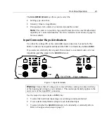
Signal input connections are made to the front panel BNC connectors, using the
V
or
A
connector for each input as desired. Each input is configured, such that the outer
shell of the connector is the input
LO
(negative) connection, and the central pin is the
input
HI
(positive) connection.
•
Reconfigure each input while no signals are present.
•
Check the configuration of each input prior to making connections, particularly
the
GUARD
connections.
Warning:
NEVER
TOUCH
the outer shell of any of the BNC connectors
(including unused ones) when signals are applied to the instrument.
Notes:
1)
Particularly when high frequency phase sensitive measurements are being made, it
is highly recommended that all cables be similar in both construction and length.
The phase shift caused by dissimilar cable lengths is of the order of 0.03° per foot at
100kHz.
2)
When measuring voltages, reduce potential interference and crosstalk between
inputs by the use of shielded cables (e.g., coaxial cable). If input capacitance is of
concern, then use tightly wound wires of small gage, twisted pairs.
3)
When measuring currents, particularly at the lower levels (10mA and less), use
tightly twisted pairs of wires of sufficient gage for the current being carried. In the
presence of severe interference, or where the current signal has significant common
mode voltage, keep the input connections as short as possible.
4)
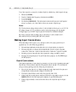
The
GUARD
connections (if any) may be made with any suitable form of
connection.
Using the Operational Keys
Whether viewing a display showing parameters, measurement results, or
configuration menu items, the method of front panel operation is the same. Refer
also to
Configuration Setup
on page 39.
Changing Displayed Information or Settings
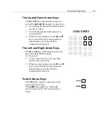
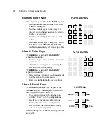
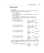
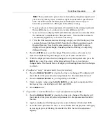
To enter changes to a configuration, press a
DISPLAY SELECT
key to place the cursor
on the line of data you are modifying. If you press the
ENTER
key once, the cursor
disappears, although the displayed menu accommodates the new data. Press a
Summary of Contents for Xitron 6000-2
Page 1: ...USER S GUIDE 6000 2 6000 3 Phase Angle Voltmeters...
Page 2: ......
Page 36: ...36 6000 2 3 User Guide Rev E...
Page 86: ...86 6000 2 3 User Guide Rev E...
Page 94: ...94 6000 2 3 User Guide Rev E...
Page 101: ...Appendix B 101...

