38
6000-2 & -3 User Guide, Rev E
Power Connection
The 6000 instrument is designed to operate with a three-conductor power cord. The
third conductor is securely connected to ground to ensure the external chassis of the
instrument remains at ground potential.
Warning:
Operation with a two-conductor power cord, or without a secure ground
connection may render the Phase Angle Voltmeter instrument unsafe for use.
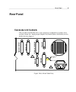
Configuration Control Switch
The Configuration Control switch allows you to disable reconfiguration of the
instrument by unauthorized users. This switch is located in the upper right-hand
corner of the rear panel. When in the
LOCKED
(upper) position the instrument’s
configuration is locked against changes, other than any caused by recalling
predefined memory locations.
The following changes are made to the menus when in the Configuration Control
switch is in the
LOCKED
position:
•
Display lines cannot be altered.
•
The
SETUP
and
STORE
keys are disabled.
•
The Nullmeter’s
SELECT
and
SCALE
keys are disabled.
•
The
CALIBRATION
menu is reduced to
System Status
and
Internal
Calibration
selections.
•
The phase
A
,
B, SYNC
and
GUARD
input keys are disabled.
Parallel Printer Interface
Use standard Centronics parallel cable compatible with IBM-PCs. This interface
option supports serial stand-alone types or PCL and compatible printers only.
RS232 Connectors
Use this connection for control or for printer output. Baud rates can be set from
1,200 to 38,400 baud. Flow control via RTS/CTS handshake. See
Interface
Operation
on page 63, for information on using this feature.
IEEE488 Connector
This connection enables full talk/listen capabilities. See
Interface Operation
on
page 63, for information on using this feature.
Summary of Contents for Xitron 6000-2
Page 1: ...USER S GUIDE 6000 2 6000 3 Phase Angle Voltmeters...
Page 2: ......
Page 36: ...36 6000 2 3 User Guide Rev E...
Page 86: ...86 6000 2 3 User Guide Rev E...
Page 94: ...94 6000 2 3 User Guide Rev E...
Page 101: ...Appendix B 101...

