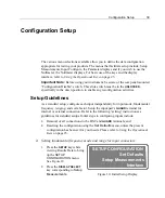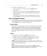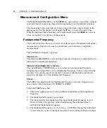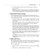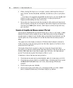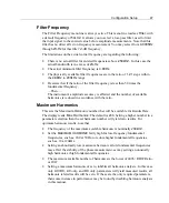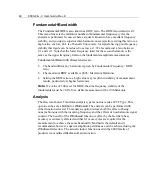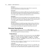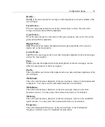
Configuration Setup
41
Ø
Setting the
input mode for each input connector:
These settings select which signal, voltage or current, is going to be measured on
which input. Additional settings in the display affect the range for voltage and
current,
Scaling
and the
Guard
connection being internal or external. Note that when
making these input settings you must call up the
INPUT CONFIGURE
display
uniquely for each input connector used. See Figure 12.
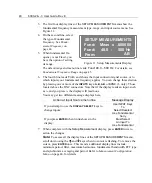
1. Press the
A
,
B
,
AB
, or
S
(-3 only) key located at the
INPUT
connectors while
viewing the Results Data.
The display now shows the
INPUT A CONFIGURE
menu
corresponding to the
A
input
key, or the one you pressed.
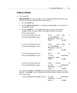
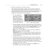
INPUT A CONFIGURE
auto ( 6m) V(dc)
Scaling x +1.0000
Guard : Lo Input A
Figure 12. Input Configure Display
2. Correlate the display’s input mode (power measurement) with the actual input.
Note that
the display shows the input configured for voltage measurements, using
DC coupling. Update the display by pressing the
DISPLAY SELECT 2
key twice
and using the
é
or
ê
keys to alter the option. The input mode choices are:
V (dc); V (ac); V (50)
and
A (dc).
Note:
Use the respective
VOLTS
BNC connector for all voltage
input
V
. Use
AMPS
input connector for the current input
A
.
Important Note:
Take care, when measuring low frequency signals, particu-
larly phase measurements. After applying a signal containing a significant DC
level, the input may take an extended period (time) to settle as the input time
constant is 300mS
±
2%.
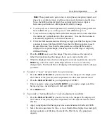
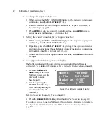
3. The default for voltage/current input range is
auto
. T
o set a fixed range value,
s
croll through the given selections. Choose a range of
6Vrms,
or higher, which
effectively creates an input impedance of 600k
Ω
. The selectable options are:
2.5;
6; 20; 65; 200; 700; 6m; 20m; 70m;
200m
; and
750m
. Note that the range
currently being used shows in brackets to the right when the selected input mode
and the in-use input mode are the same.
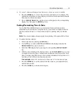
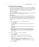
4. Press
ENTER
once to move onto the next display line, press
ENTER
twice to
action changes for the separate input connections.
Summary of Contents for Xitron 6000-2
Page 1: ...USER S GUIDE 6000 2 6000 3 Phase Angle Voltmeters...
Page 2: ......
Page 36: ...36 6000 2 3 User Guide Rev E...
Page 86: ...86 6000 2 3 User Guide Rev E...
Page 94: ...94 6000 2 3 User Guide Rev E...
Page 101: ...Appendix B 101...

