42
6000-2 & -3 User Guide, Rev E
Ø
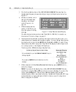
To change the (input) scale factor:
1. While viewing the
INPUT CONFIGURE
display for the respective input you are
configuring, press the
DISPLAY SELECT 3
key.
2. Enter the desired scale factor using the
DATA ENTRY
keypad. For details, see
Input
Scaling
on page 43.
3. Press
ENTER
once to move onto the next display line, press
ENTER
twice to
action changes for the separate input connections.
Ø
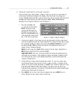
Setting the Guard
connection for each input connector:
1. While viewing the
INPUT CONFIGURE
display for the respective input you are
configuring, press the
DISPLAY SELECT 4
key.
2. Repetitively press the
DISPLAY SELECT 4
key to toggle the options for external
and internal connections. Choose
External,
or one of the internal connections:
Lo Input A, Lo Input B
, or
Lo Input Sync (-
3 only).
3.
When complete with your input connector selections, press
ENTER
to action the
changes.
Ø
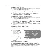
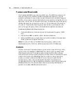
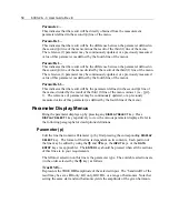
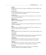
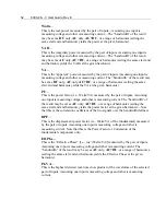
To configure the Nullmeter parameter display:
The Nullmeter does not light until valid measurements for Results Data are
configured. For details on the options, refer to
Nullmeter Display Menu
on page 49.
1. Press the
NULLMETER
SELECT
key. One of five
Nullmeter parameter dis-
plays will come up.
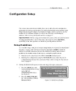
See Figure 13.
2. Continue pressing the
DISPLAY SELECT 1
key to
view the four possible par-
ameter displays for the
Nullmeter.
Nullmtr:- Parameter
p = Phs Bh01--Ah01
Display as +/-180
o
Filter = 0.000s
Figure 13. Nullmeter Sample Display
Refer to
Nullmeter Parameter Types
on page 49.
4. Press the
NULLMETER SCALE
key. Refer back to
The Nullmeter
on page 22.
If you do not choose to use the Nullmeter, then configure a Parameter (p) display to
match your measurement requirements. Refer to
Parameter Display Menus
on
page 50.
Summary of Contents for Xitron 6000-2
Page 1: ...USER S GUIDE 6000 2 6000 3 Phase Angle Voltmeters...
Page 2: ......
Page 36: ...36 6000 2 3 User Guide Rev E...
Page 86: ...86 6000 2 3 User Guide Rev E...
Page 94: ...94 6000 2 3 User Guide Rev E...
Page 101: ...Appendix B 101...


