Configuration Setup
43
Ø
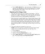
To complete a configuration setup:
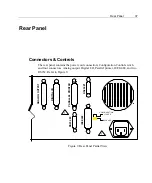
1. Connect the signal(s) to the respective BNC and
GUARD
terminals.
2. Apply signals.
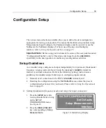
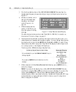
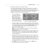
3. Make any adjustments required to
SETUP MEASUREMENT
configuration.
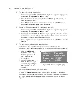
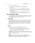
4. Make adjustments, as needed to the parameter displays or the Nullmeter
parameter displays.
5. When complete with this setup store the configuration using the Control
keypad’s
STORE
key. See
Storing & Retrieving Configurations
on page 32.
Input Configuration Menu
Each selectable option of the Input Configuration menu is described in the following
subsections. When the displayed menu has been altered to suit your requirements,
press the
ENTER
key twice to action any changes made.
Input Scaling
This indicates the present amplitude scale factor (if any) applied to measurements of
this input. If the default scale factor of
+1.0
shows in the display, then no input
scaling is performed. You may enter any desired scale factor (including negative
factors) for application to each input. Negative scale factors are correctly applied,
such as, the corresponding positive scale factor is applied, in concert with a 180°
phase shift.
Guard
This indicates the presently selected
GUARD
terminal connection.
•
External
—
Indicates that the
GUARD
terminal is to be externally driven.
•
Lo Input
A, B
or
S (-3)
—
Indicates that the
GUARD
terminal is internally
connected to the respective input’s BNC outer shell.
Caution:
If you are measuring current, or if the voltage range is less than 6vrms,
ensure that less than 10Vpk exists between each BNC outer shell of the pair of inputs
and outer shell and the guard terminal.
Notes:
1)
When making external connections only connect to the
GUARD
terminals.
2)
When using the current input, current low MUST be externally connected to the
GUARD
terminal and the input pair configured to use external guard.
Summary of Contents for Xitron 6000-2
Page 1: ...USER S GUIDE 6000 2 6000 3 Phase Angle Voltmeters...
Page 2: ......
Page 36: ...36 6000 2 3 User Guide Rev E...
Page 86: ...86 6000 2 3 User Guide Rev E...
Page 94: ...94 6000 2 3 User Guide Rev E...
Page 101: ...Appendix B 101...

