92
6000-2 & -3 User Guide, Rev E
•
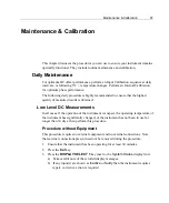
Ensure that the correct input connector is used for each step, all voltage
calibration steps use the respective V BNC connector, while all current
calibration steps use the respective A BNC connector.
•
Although multiple inputs are allowed, calibrate only one input at a time.
NEVER connect any inputs in parallel for other than normal voltage
calibration points.
•
Particularly when performing the 50
Ω
voltage input steps, ensure that the
BNC input connector is properly seated, is clean and is clear of corrosion, at
both the instrument and the source ends of the cable.
•
The
GUARD
terminals of the instrument are automatically set for external
connection during this procedure; these should be tied to the
GUARD
or
other suitable terminal on the source during the entire procedure.
•
This procedure includes calibrations with high accuracy at low voltage
levels. Ensure that there are no significant noise sources nearby with
frequencies close to the calibration frequency.
•
During the procedure, the input range of the instrument is held at that
required for the calibration level. When changing input connections, or
stepping the instrument to the next calibration step, the
Overload
light may
illuminate momentarily, this should be disregarded. If Overload remains
illuminated during the calibration step, then investigate a cause. The
instrument’s internal protection systems are enabled at all times, thus no
damage to the instrument will result unless the specified overload abilities of
the instrument are exceeded.
4. Repeat steps 5 through 8 for each input listed in the display (the
Sync
input is
denoted by the letter
S
).
5. Ensuring that the calibration source is in Standby, or otherwise has its output
disabled, attach the calibration source’s output terminals to the input of input
terminals when
Input Applied?
shows in the display.
6. Set the calibration source’s output level to that displayed in the uppermost line
of the display and allow time for the source to settle to within the required
accuracy.
7. For the input being calibrated, press the
DISPLAY SELECT
key next to the line for
that input. The 6000 instrument will now display the actually measured input
level and the percentage deviation of the instrument at that level.
8. After allowing the displayed values to settle, a few seconds, press the
DISPLAY
SELECT
key next to the line for that input. That display line will then change to
Completed
. If the calibration results with an out of tolerance condition within
the instrument, then an error message will be issued and that input will not be
available for external calibration for the remainder of the procedure.
Summary of Contents for Xitron 6000-2
Page 1: ...USER S GUIDE 6000 2 6000 3 Phase Angle Voltmeters...
Page 2: ......
Page 36: ...36 6000 2 3 User Guide Rev E...
Page 86: ...86 6000 2 3 User Guide Rev E...
Page 94: ...94 6000 2 3 User Guide Rev E...
Page 101: ...Appendix B 101...


