24
6000-2 & -3 User Guide, Rev E
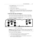
View the respective connector’s indicator lights to determine, which input is being:
•
Measured (
IN USE
);
•
Used for fundamental frequency determination (
SYNC
);
•
Scaled (
SCALED
);
•
Overloaded (
OVERLOAD
). The instrument automatically protects itself against
serious overload, even when held on the most sensitive input range
Notes:
1)
The maximum voltage between the
GUARD
terminal and an
Input Low
is 10V for
all voltage ranges of 2.5V and below, and for all current ranges. On the higher
voltage ranges, up to 1000V may be present between the terminal and input.
2)
Noisy and inaccurate readings may result if the
GUARD
terminal is left
disconnected when external guard has been selected.
Making Input Connections
When deciding which inputs to use, attempt to follow the same pattern for all
applications. Use the following guidelines:
•
If measuring amplitudes and/or distortion of a single signal, use input
A
.
•
If measuring phase (or phase related amplitudes) between a pair of signals,
connect the ‘reference’ signal to input
A
and the “unknown” signal to input
B
.
•
If making a power measurement, use input
A
for voltage and
B
for current.
•
If using a third signal purely for synchronization purposes, use the
SYNC
input
for this purpose.
Guard Connections
The input capacitance of each input to ground is very low (a few hundred picofarads)
thus the use of an external connection for guard is rarely needed. We recommend
using external guarding under the following circumstances:
•
If low level (less than 1V or 10mA) signals are being measured in the presence
of significant common mode voltages or interference.
•
The input connections are extremely long (greater than 10ft).
•
When using the current input, current low MUST be externally connected to the
GUARD
terminal. And the input pair configured to use
External
guard
•
When using internally connected Guard, choose the input having the largest
signal.
Summary of Contents for Xitron 6000-2
Page 1: ...USER S GUIDE 6000 2 6000 3 Phase Angle Voltmeters...
Page 2: ......
Page 36: ...36 6000 2 3 User Guide Rev E...
Page 86: ...86 6000 2 3 User Guide Rev E...
Page 94: ...94 6000 2 3 User Guide Rev E...
Page 101: ...Appendix B 101...


