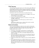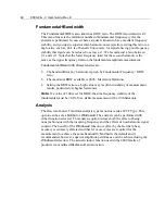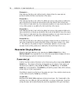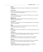
Configuration Setup
39
Configuration Setup
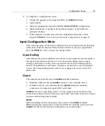
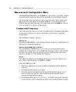
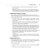
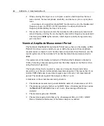
The various menu selections available allow you to define the data configuration
appropriate for testing your products. The menus that facilitate setup include: Setup
Measurements, Input Configure, the Parameter displays and if you wish to use the
Nullmeter, the Nullmeter displays. For basic use of the keys and the display
interface, refer to
Using the Operational Keys
on page 25.
Important Note:
Before using your instrument, be aware of the rear panel mounted
“Configuration Disable” switch. This slide switch must be in the
UNLOCKED
,
specifically in the down position, to enable any reconfiguration activities.
Setup Guidelines
As a standard setup, configure each input independently for input mode, fundamental
frequency, ranging, and scale factor. Setup the input pair’s
GUARD
terminal for
internal or external connection. Refer to the following “setting” instructions as
guidelines for standard setups. Initial steps to configuring inputs include:
•
Removal of all connections to the BNC and
GUARD
terminals; and
•
Resetting the configuration using the
Set Defaults
menu, unless the present
configuration has been set for your needs. Please refer to
Using the Operational
Keys
on page 25.
Ø
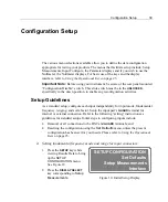
Setting fundamental frequency mode and range for input connectors:
1. Press the
SETUP
key while
viewing Results Data to bring
up the
SETUP
CONFIGURATION
menu.
See Figure 10.
2. Press the
DISPLAY SELECT
key corresponding to
Setup
Measurements.
SETUP CONFIGURATION
Set Defaults
Setup Measurements
Interface
Figure 10. Initial Setup Display
Summary of Contents for Xitron 6000-2
Page 1: ...USER S GUIDE 6000 2 6000 3 Phase Angle Voltmeters...
Page 2: ......
Page 36: ...36 6000 2 3 User Guide Rev E...
Page 86: ...86 6000 2 3 User Guide Rev E...
Page 94: ...94 6000 2 3 User Guide Rev E...
Page 101: ...Appendix B 101...


