EN
20
3.
WIRING CONNECTIONS
3.1
Vca Compressor
The Vca compressor doesn’t have a control unit and can be powered only by the Vca
current though the cable with plug.
3.2
Compressor with control unit
Introduction
The compressor provided must always be powered via the electronic control unit that
is supplied with the unit. Never connect the compressor pins directly to the poles of a
battery or any other AC or DC power source. Never connect other types of control unit.
Always respect the battery polarity with the control unit terminals; the compressor is
protected against brief accidental polarity inversions, however, such inversions can
cause the control unit and/or compressor to break. The different control unit models
can be powered as follows:
•
12/24 V DC
•
12/24 V DC and 100-240 V AC
•
12-42 V DC
We also recommend positioning a fuse between the positive battery pole or feeder and
the positive supply terminal of the electronic control unit. For vehicles with chassis
connected to the positive terminal (+) of the battery, position a fuse between the
negative pole of the battery or feeder and the negative supply terminal of the electronic
control unit. For BD35 and BD50 compressor models, use fuses with the following
amperage:
Power (V)
Fuse (A)
12 V DC
15 A
24 V DC
7.5 A
For the GD30 FDC compressor, use fuses with the following characteristics:
Power (V)
Fuse (A)
12 V DC
30 A
24 V DC
15 A
42 V DC
10 A
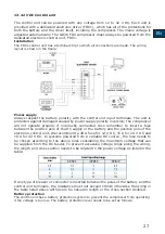
12/24 V DC Control unit
The electronic control unit is a dual voltage device. This means that the same unit can
be used in both 12V and 24V power supply systems. The maximum voltage for 12
V systems is 17 V, while for 24 V systems it is 31.5 V. Maximum permitted ambient
temperature is 55°C. The electronic control unit is equipped with an incorporated
thermal breaker to stop the compressor in case of overheating.
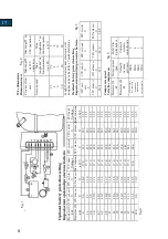
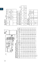
Installation (fig. 1)
Connect the terminal plug from the electronic unit to the compressor terminal. Fit the
electronic unit on the compressor by snapping the cover over the screw head (1).
Summary of Contents for ND35H2O
Page 15: ...IT 15 4 3 Collegamento eletrico...
Page 29: ...EN 29 4 3 wired diagram...
Page 43: ...FR 43 4 3 Raccordement lectrique...
Page 44: ...44...
Page 46: ...46...

