Indoor unit installation
96
Installation
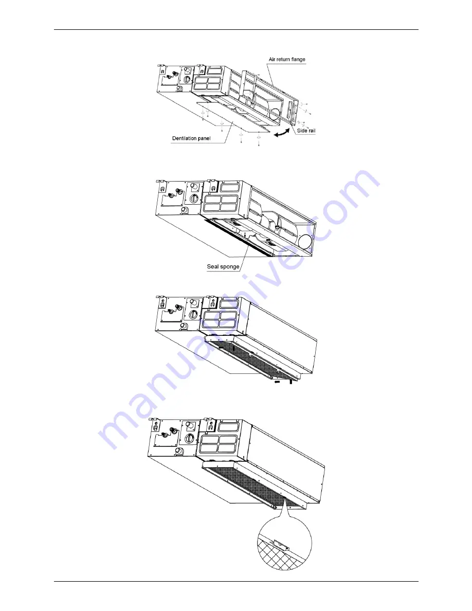
3.2.7 Change the air inlet direction
①
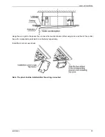
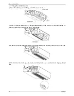
Take off ventilation panel and flange, cut off the staples at side rail.
②
Stick the attached seal sponge as per the indicating place in the following fig, and then change the
mounting positions of air return panel and air return flange .
③
When install the filter mesh, please plug it into flange inclined from air return opening, and then push up.
④
The installation has finish, upon filter mesh which fixing blocks have been insert to the flange positional
holes.
Summary of Contents for ACP-12CC35AECI
Page 2: ......
Page 4: ......
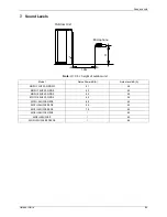
Page 15: ...Service Space 12 Indoor Units 3 Service Space 1000mm 1000mm 1000mm 1000m m ...
Page 18: ...Air Velocity Distributions Reference Data Indoor Units 15 30 42K Cooling Heating ...
Page 19: ...Air Velocity Distributions Reference Data 16 Indoor Units 48 55K Cooling Heating ...
Page 24: ...Field Wiring Indoor Units 21 10 Field Wiring ...
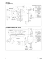
Page 31: ...Wiring Diagrams 28 Indoor Units 4 Wiring Diagrams MTBU 12HWFN1 QRD0W MTB 18HWFN1 QRD0 ...
Page 33: ...Static Pressure 30 Indoor Units 5 Static Pressure MTBU 12HWFN1 QRD0W MTB 18HWFN1 QRD0 ...
Page 34: ...Static Pressure Indoor Units 31 MTB 24HWFN1 QRD0 MTB 30HWFN1 QRD0 ...
Page 44: ...Service Space Indoor Units 41 3 Service Space ...
Page 46: ...Wiring Diagrams Indoor Units 43 Pre setting Instructions ...
Page 55: ...52 Indoor Units 10 Field Wiring ...
Page 59: ...Service Space 56 Indoor Units 3 Service Space ...
Page 60: ...Wiring Diagrams Indoor Units 57 4 Wiring Diagrams ACP 12CC35AECI ACP 18CC50AECI ...
Page 64: ...Field Wiring Indoor Units 61 10 Field Wiring ACP 12CC35AECI ACP 18CC50AECI ...
Page 68: ...Dimensions Console Type 65 2 Dimensions 16 Drain pipe 195 Hanging arm Unit mm 700 600 210 ...
Page 69: ...Service Space 66 Console Type 3 Service Space ...
Page 70: ...Wiring Diagrams Console Type 67 4 Wiring Diagrams MFAU 12HRFN1 QRD0W ...
Page 75: ...Field Wiring 72 Console Type 10 Field Wiring MFAU 12HRFN1 QRD0W ...
Page 81: ...Wiring Diagrams 78 Outdoor Units 4 Wiring Diagrams MOZU 12HFN1 QRD0W MOZU 18HFN1 QRD0 ...
Page 82: ...Wiring Diagrams Outdoor Units 79 MOFU 24HFN1 QRD0 MOYU 30HFN1 QRD0 ...
Page 83: ...Wiring Diagrams 80 Outdoor Units MOYU 36HFN1 QRD0 ...
Page 84: ...Wiring Diagrams Outdoor Units 81 MOYU 36HFN1 RRD0 MOYU 42HFN1 RRD0 ...
Page 85: ...Wiring Diagrams 82 Outdoor Units MOEU 48HFN1 QRD0 MOEU 48HFN1 R MOEU 55HFN1 RRD0RD0 ...
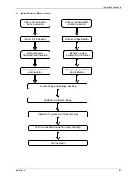
Page 111: ...Refrigerant pipe installation 108 Installation ...
Page 151: ...Troubleshooting 148 Electrical Control System 2 4 4 3 E3 malfunction ...
Page 155: ...Troubleshooting 152 Electrical Control System 2 4 4 8 P1 malfunction For 36k models ...
Page 161: ...Troubleshooting 158 Electrical Control System 2 4 4 14 P7 malfunction ...
Page 174: ...www VIVAX com ...

