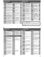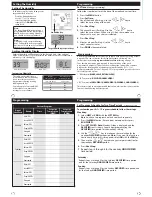
Installation Tips
The low battery indicator is displayed when the AA battery power is low. If the user
fails to replace the battery within 21 days, the screen will only show the low battery
indicator but maintain all functionality. If the user fails to replace the batteries after
an additional 21 days (days 22-42 since first “low battery” display) the setpoints will
change to 55˚F (Heating) and 85˚F (Cooling). If the user adjusts the setpoint away from
either of these, it will hold for 4 hours then return to either 55˚F or 85˚F. After day 63
the batteries must be replaced immediately to avoid freezing or overheating because
the thermostat will shut the unit off until the batteries are changed.
Important
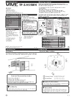
Indicates the current room temperature
Time and day of the week
REMOTE
indicates a remote has control of the system.
System Operation Indicators:
The
COOL
,
HEAT
or
FAN
icon will display
when the
COOL
,
HEAT
or
FAN
is on.
NOTE:
The compressor delay feature is
active if these icons are flashing. The compressor will not turn on until the 5
minute delay has elapsed.
Setpoint:
Displays the user selectable setpoint temperature
HOLD
is displayed when thermostat program is permanently overriden.
1
2
3
7
9
Low Battery Indicator:
Replace batterieswhen this indicator is shown.
Program Menu Options:
Show different options during programming.
Period Icons -
This thermostat can have 2 or 4 programmable time periods
per day. Icons are displayed for 4 time periods. Occupied and unoccupied
will display in the text field for 2 time periods.
8
Getting to know your thermostat
Installation Tips
Thermostat Quick Reference
F C
REMOTE
HOLD
Mon Tue Wed Thu Fri Sat Sun
Technician
Setup
Next Step
Set Time
Next Zone
Set Schedule
Hold
Previous Step
Run Schedule
Menu
Done
Auto
On
Heat
Off
Cool
Auto
Em. Heat
Clean
Display
Humidity
+1 +2
LEAVE
RETURN
SLEEP
WAKE
2
3
7
9
Thermostat Quick Reference
Getting to know your thermostat
Glow in the dark light button
Fan key
System key
Setpoint keys
Menu key
LCD Display
1
2
3
Scheduled time period Icons
7
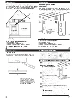
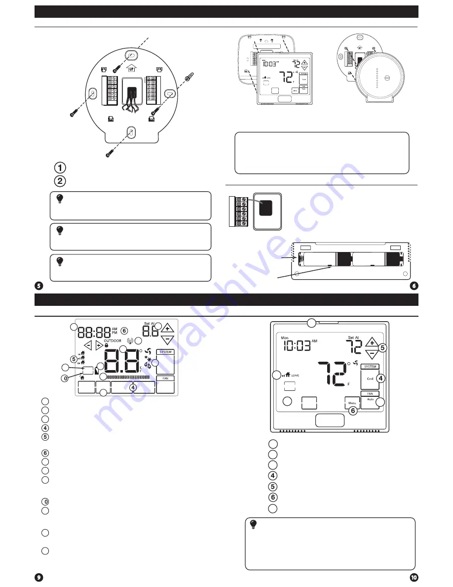
Base Module Subbase installation
Vertical Mount
Horizontal Mount
For horizontal mount put one screw on
the left and one screw on the right.
For vertical mount put one screw on
the top and one screw on the bottom.
To connect the base module to the master thermostat, refer to the
directions on page 13 of this manual.
Note:
Wire the base module’s subbase the same way you would wire a
hardwired thermostat subase.
Wiring Note
The base module must be hardwired (C and R terminals connected to
24V power.)
Note:
Align the 4 tabs on the subbase with corresponding slots on
the back of the thermostat/base module, then push gently until
it snaps in place.
Note:
To ensure a solid fit between the thermostat/base module
and the subbase:
1.
Mount subbase to a flat wall
2.
Use screws provided
3.
Drywall anchors should be flush with the wall
4.
Wires should be pushed into the wall
Mount Thermostat and Base Module
Battery installation is optional if there are no remotes
connected to the Master Thermostat (C terminal con-
nected).
If you connect an outdoor remote and/or
indoor remote sensors it is required the
thermostat be hardwired.
Important:
High quality alkaline batteries are
recommended. Rechargeable batteries or low quality
batteries do not guarantee a 1-year life span.
Insert 2 AA Alkaline
batteries (included). High
quality alkaline batteries
are recommended.
On the back of the
thermostat insert 2
AA Alkaline batteries
(included).
Battery Installation
11
1
Humidity
: Shows the humidity target setpoint settings and keys.
1
Clean Display:
Pressing
CLEAN DISPLAY
will allow 30 seconds to clean the
display. The keys will be inoperable during this time.
CLEAN
will appear if
your contractor has programmed a filter change reminder. Press
CLEAN
when filter has been replaced to reset the filter change reminder timer.
12
12
Next Zone:
This button will appear if optional indoor remotes are
present. By selecting
NEXT ZONE
you can cycle through each of the zones
set up during the initial installation.
13
System Information:
Shows which zone or zones are controlling your
system. Shown only when one or more indoor sensors are connected.
13
1
8
H
D
Y1
Y2
W1/E
Pro1 Base Module
for use with T955WH
W2
G
O
B
11
Temperature
Set Time
Next Zone
Clean
Display
Humidity
Temperature
Set Time
Next Zone
Clean
Display
Humidity
1
2
3
7

