d)
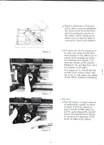
Next,
lift
up
the
friction
roller
bar
and
open
the
left
and
right
tractor
covers
by lifting
them
up
and
turning
them
to
the
out-
side
(figure
15).
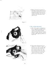
e)
With
the
holes
along
both
edges
of
the
paper
matched
up
with
the
paper
feed
pins
on
the
left
and
right
tractors,
close
the
trac-
tor
covers.
Lower
the
friction
roller
bar,
positioning
the
fric-
tion
rollers
on
the
bar
so
that
they
rest
directly
on
top
of the
two
large
rubber
tractor
rings
(figures
15
and
16).
If
the
tractor
spacing
does
not
match
the
paper
width,
slide
the
tractors
to
the
left
or
right
as
needed.
Make
sure
that
the
paper
is
positioned
so
that
the
first
and
last
positions
are
on
the
paper.
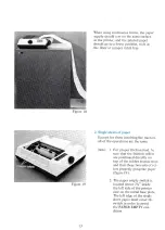
f)
Return
the
head
adjustment
lever
to
its
original
position.
Replace
the
paper
shelf
and
printer
cover
in that
order
(figure
17).
Adjust
the
print position
by turning
the
paper
feed
knob.
Figure
17
12


