background image


ViVOpay Kiosk II User Guide 


631-0071-00 

ViVOtech Proprietary 

Page


11 of 19


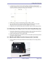
63.50 [ 2.500 

]

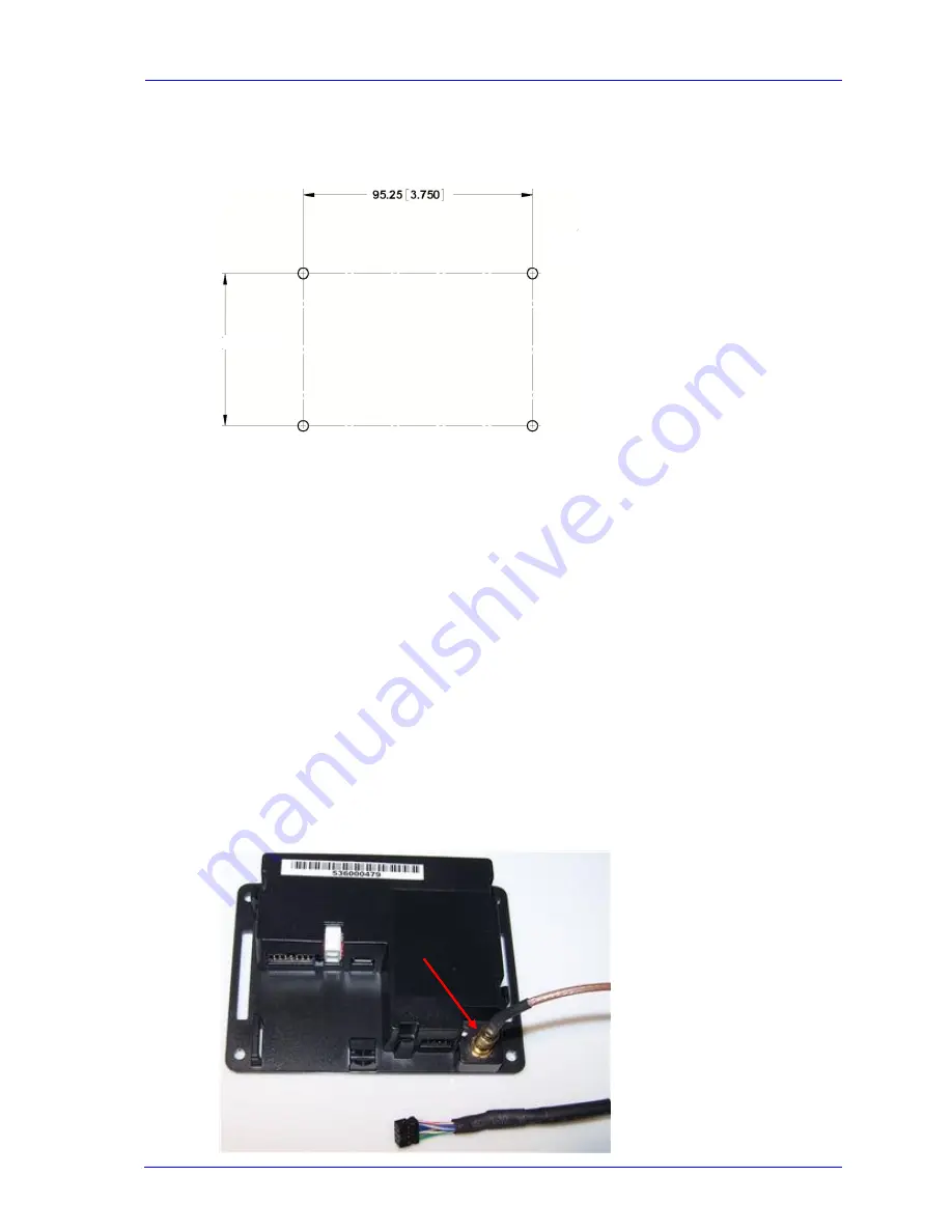
2.  Locate the four 4.4mm (0.173 inch) mounting holes by holding the ViVOpay Kiosk II 

Controller in position and mark the holes. The following diagram shows the spacing on the 
holes to be drilled for mounting the ViVOpay Kiosk II Controller. 


3.  Drill the four 4.4 mm (0.173) mounting holes using a number 17 drill bit. 

4.  Use four screws and nuts to mount the ViVOpay Kiosk II Controller to the kiosk surface. 

(Mounting screws are not provided and must be supplied by the installer.) 

5.  Tighten the nuts to hold the ViVOpay Kiosk II Controller in position so that it does not move. 


2.3.2  Mounting the ViVOpay Kiosk II Controller Using Mounting Tape 


1.  Position the ViVOpay Kiosk II Controller on the interior of the kiosk making sure that there 

is sufficient room for the antenna mounting surface to be fully opened. 

2.  Attach double-sided tape to the mounting surface. 

3.  Position the ViVOpay Kiosk II Controller over the mounting tape and gently apply pressure 

to hold the controller in position. 

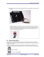
2.4  Attaching the Cables from the Antenna to the Controller 


1.  Attach the SMB end of the cable 

(

220-2457-00

)

 from the antenna to the ViVOpay Kiosk II 

Controller. 


Summary of Contents for Kiosk II

Page 1: ...Publication number 631 0071 00 Revision 2 September 2011 ViVOpay Kiosk II User Guide ViVOtech Inc 451 El Camino Real Santa Clara CA 95050 Email info vivotech com URL www vivotech com ...

Page 2: ...pt as permitted by such license no part of this publication may be reproduced or transmitted by electronic mechanical recording or otherwise or translated into any language form without the express written consent of ViVOtech Inc ViVOtech ViVOwallet ViVOpay ViVOplatform and ViVOadmin are trademarks or registered trademarks of ViVOtech Inc Warranty Disclaimer The services and hardware are provided ...

Page 3: ...ning the equipment off and on the user is encouraged to try and correct the interference by one or more of the following measures Reorient or relocate the receiving antenna Increase the separation between the equipment and the receiver Connect the equipment into an outlet on a circuit different from that to which the receiver is connected Consult the dealer or an experienced radio TV technician fo...

Page 4: ...ng the ViVOpay Kiosk II Controller Using Screws 10 2 3 2 Mounting the ViVOpay Kiosk II Controller Using Mounting Tape 11 2 4 Attaching the Cables from the Antenna to the Controller 11 2 5 Connecting to Power 12 2 6 Connecting to the Data Port 13 2 7 Using the ViVOpay Kiosk II to Make a Purchase 14 2 7 1 Presenting Cards Fobs or NFC Phones 14 2 7 2 Making a Purchase 14 3 Installation Points 15 4 RF...

Page 5: ...he ViVOpay Kiosk II is designed to support a wide input power range Both data and power can be supplied via a single cable to reducing the effort and complexity of installation 1 1 Features Supports ISO 14443 Type A Type B MiFare and NFC based contactless transactions 32 bit Microcontroller with ample memory capable of supporting future application upgrades Crypto data processing for contactless E...

Page 6: ... A Modified Manchester ISO 14443 2 Type B NRZ L BPSK Typical Read Range 4 6 cm 1 5 to 2 3 inches Physical Controller Height 105 mm 4 13 inches Width 76 2 mm 3 00 inches Depth 22 5 mm 0 88 inches Square Bezel Antenna Height 75 mm 2 95 inches Width 60 mm 2 36 inches Depth 16 8 mm 0 66 inches Angle Bezel Antenna Height 96 2 3 787 inches Width 82 3 3 24 inches Depth 16 8 mm 0 66 inches Environmental O...

Page 7: ...st Verify that you have the following hardware for the installation of the ViVOpay Kiosk II ViVOpay Kiosk II Controller ViVOpay Kiosk II Antenna either square or angle bezel Antenna LED power and data cable ViVOpay Kiosk II to ECR POS cable customer supplied This USB or serial cable varies based on the host to be used Drill Template for the antenna 630 1046 00 Square Bezel Antenna Angle Bezel Ante...

Page 8: ...tenna 630 1046 00 locate and mark the four 4 4mm 0 173 inch mounting holes 2 Using the Drill Template locate and mark the two 14 0 mm 0 551 inches access holes used for connecting the antenna power and the LED power and data cable to the ViVOpay Kiosk II 3 Drill the four 4 4 mm 0 173 mounting holes using a number 17 drill bit 4 Drill the two 14 0 mm 0 551 inch holes using a 35 64 drill bit 5 Remov...

Page 9: ...ace of the kiosk Make sure to tighten the nuts securely so that the ViVOpay Kiosk II does not move on the outside surface of the kiosk If you are installing the Angle Bezel Antenna tighten the nuts to 5 7 in lbs for a good weather seal 9 Attach the end of the cable with the SMB connector through the right 14 0 mm 0 551 inch hole and attach it to the socket on the back of the ViVOpay Kiosk II anten...

Page 10: ...n a full scale installation 2 3 Mounting the ViVOpay Kiosk II Controller Note The ViVOpay Kiosk II Controller must be mounted within 1 meter of the antenna If the antenna is mounted of a surface that opens such as a door make sure the controller and antenna are close enough that there is no tension on the cable when the enclosure is open If it is acceptable the installer can drill four holes for m...

Page 11: ...provided and must be supplied by the installer 5 Tighten the nuts to hold the ViVOpay Kiosk II Controller in position so that it does not move 2 3 2 Mounting the ViVOpay Kiosk II Controller Using Mounting Tape 1 Position the ViVOpay Kiosk II Controller on the interior of the kiosk making sure that there is sufficient room for the antenna mounting surface to be fully opened 2 Attach double sided ta...

Page 12: ...If the cable is installed incorrectly upside down it will apply the wrong polarity to the LEDs and damage them 2 5 Connecting to Power The KIOSK II can be powered through the serial communications port or the two socket power connector If you are using USB data communications you must power the KIOSK II though the two socket power connector Connect 7 5 to 36VDC to the white two socket Molex connec...

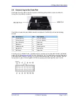
Page 13: ... 7 5v to 36VDC 3 Power ground 4 7 5v to 36VDC 5 No connection 6 Reserved 7 Reserved 8 Reserved 9 Signal ground 10 Signal ground 11 RS 232 Tx 12 RS 232 Rx 13 ISP Input 14 Reserved To build your own RS 232 cable use Molex female connector part number 0511101451 with 50394 series crimps see www molex com for more information Pin 1 is indicated by a triangle diagram is socket side view of female conne...

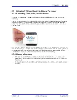
Page 14: ...te briefly to indicate a successful test This tests the antenna s ability to read the RFID test card If unsuccessful there will be no reaction from the reader If you use a test card and the ViVOpay reader is attached to the ViVOpay Kiosk II Controller a dummy transaction can be tested The transaction will not be authorized and will come back with a response but will at least test for end to end co...

Page 15: ... are inaccessible and invisible to customers Label the cable ends host ViVOpay and power to simplify connection testing or component replacement Test the ViVOpay Kiosk II installation using a test card to perform an end to end transaction the same as an actual purchase on the Kiosk The kiosk control panel should display Requesting Authorization Even if the transaction is declined as it should be w...

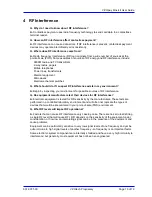
Page 16: ...Begin by inspecting your environment for possible sources of RF interference Q Do equipment manufacturers test their devices for RF interference A Electronic equipment is tested for RFI sensitivity by the manufacturers These tests are performed in a controlled laboratory environment and will often not replicate the types of devices that would be encountered in your point of sale POS environment Q ...

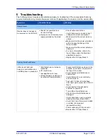
Page 17: ...re information refer to the Input Voltage under the Electrical specification section Replace the ViVOpay Kiosk II Reading Cards Fobs Phones LEDs do not light and beeper is not audible when card fob phone is presented Card fob phone not properly presented RF interference Unsupported card used Wrong firmware contact your local support representative Present card fob phone closer to the antenna and e...

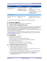
Page 18: ...he ViVOpay Kiosk II powers on it enters download mode Otherwise it will operate normally emitting a beep and flashing LEDs when powered on If you want to build your own download cable the pinouts to the external connector are given in Connecting to the Data Port After you have entered download mode you must erase the current firmware and install the new firmware 6 1 1 Preparation To install the ne...

Page 19: ...er connector and try again 9 Click Erase This erases the old firmware on the reader A message indicates a successful erase 10 Click Blank Check with Entire Device selected to confirm that the erase function worked properly 11 In the Flash Programming box click the box to select the firmware file you want to load on the ViVOpay Kiosk II 12 Click Upload to Flash to load the firmware on the reader th...

Reviews: