


VIVOTEK–Built with Reliability
User's Manual–1
Rev. 1.6.1.11
Rev. 1.0
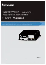
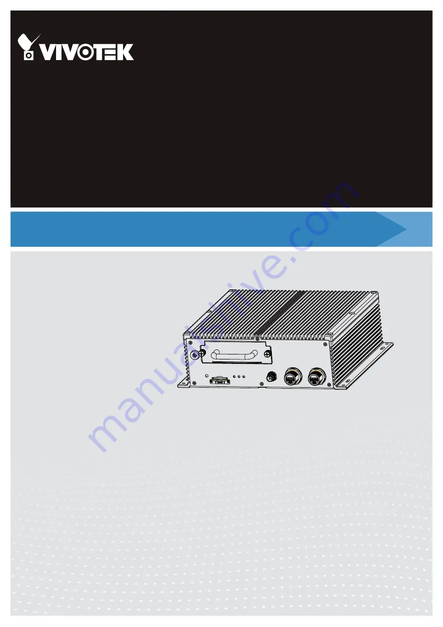
User’s Manual
H.265/H.264 Codec
• 802.3af/at PoE •
HDMI/VGA
• G-sensor • GPS • 8/16 CH • -40ºC ~ 55ºC • EN50155
Solid Connection for Shock & Vibration • SATA or SSD • Programmable Delay ON/Off
Mobile NVR
NV9311P, NV9411P
NV9311P-M12, NV9411P-M12
Rev. 1.1


