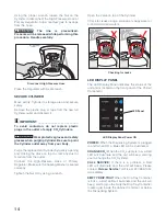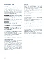
10
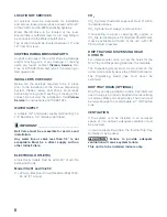
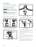
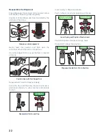
Ensure the Sealing Washers are positioned
between the Gas Regulator / Regulator Hose and
Cylinder and connect the Cylinder.
Regulator
Sealing
Washers
CO
2
Cylinder
Sealing Washer Locations
Connect the Regulator to the unit using the supplied
Installation Kit. Tighten all connections.
In the event of a CO
2
leak, close the Cylinder Valve,
retighten connection(s) and retest. If leak persists,
report leak to Vivreau.
CO
2
Pressure
: 65 PSI. Adjust Regulator as needed.
WATER
The Vivreau V3-201 and V3-202 Dispensing Systems
provide back-flow prevention, however, it must
be installed with adequate back-flow protection to
comply with applicable Federal, State and Local
Codes. Additional back-flow prevention must be
installed prior to connecting the unit to the water
supply.
The water supply to the unit must be cold, potable
water with an accessible Shutoff Valve.
Water connection to the supply is 1/2” FNPT. Water
Inlet connection to the unit is 3/8” tube. A Retaining
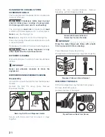
Clip must be used to attach the tube within the
connection on the unit.
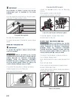
Retaining Clip
Retaining Clip Location
Insulate the pipe to prevent condensation.
The supply water pressure must be 50 PSI minimum
with a minimum flow of 1.5 gal/min. A Booster Pump
(for low pressure) or Pressure Regulator (for high
pressure) may be required to ensure the pressure.
IMPORTANT ________________________
Only connect water supply to the unit after
filling the Internal Water Tank with the water
supply line. (See Connection and Start-Up)
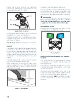
DISPENSING HEAD
Assemble and mount Dispensing Head, making
sure Dispensers are tight and straight.
Dispensing Heads
UNDER-COUNTER INSTALLATION (MODEL
V3-202)
The Under-Counter Cooler/Carbonator System
is intended to be located directly under the
Dispensing Head.
The Drip Tray is positioned in the counter under
the Dispensing Head and should have lateral play
of no more than 1/8”.
Dispensing Head Connection Tubes are to be
connected to the Under-Counter System directly
using the Installation Kit supplied by Vivreau.
Adequate ventilation
must
be provided in under-
counter installations to prevent excessive heat
build-up.
Summary of Contents for V3-202
Page 1: ...1 V3 201 and 202 Dispensing Systems Service Manual ...
Page 41: ...41 ...


