background image

22

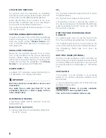
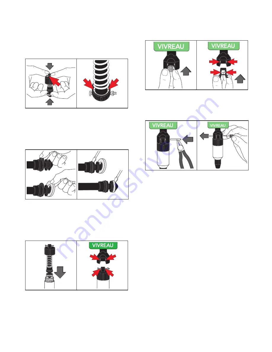
Reassemble the Dispenser

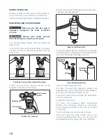
Press Dispenser Collar down firmly, reinsert screw 

and release the spring pressure gently. 
Alignment of the dimple and hole illustrated by the 

position of the Screw.

Dimple and Hole alignment

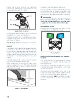
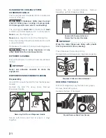
Gently feed into position and then work the 

remainder around the piston into groove.

Use a flat edged tool to ensure the Seal is located 

correctly.

Position Seal with Flat Edged Tool

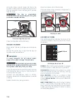
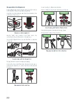
Reassemble Piston to Dispenser Body.
Screw the Cap onto the body. Ensure the Screw is 

positioned properly to allow internal components 

to align.

Reassemble Piston and Cap

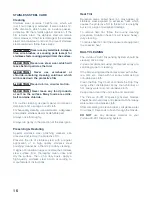
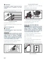
Insert spring in Dispense Handle.
Push in Plastic Insert and position with Screw.

Insert Spring and Position Plastic Insert

Position Dispense Handle and align holes.
Drive Roll Pin back into position. 

Dispense Handle Roll, Pin In Position

Summary of Contents for V3-202

Page 1: ...1 V3 201 and 202 Dispensing Systems Service Manual ...

Page 2: ...ved Any and all information contained within this document is subject to change without prior notice IMPORTANT_______________ The information contained in this manual is specific to your system It is IMPORTANT you READ FOLLOW and UNDERSTAND the instructions given This manual and all material provided with your system should be retained in a convenient location for future reference Contact Vivreau ...

Page 3: ...tion technicians should service this unit WARNING ALL WIRING AND PLUMBING MUST CONFORM TO NATIONAL AND LOCAL CODES FAILURE TO COMPLY COULD RESULT IN SERIOUS INJURY DEATH OR EQUIPMENT DAMAGE SAFETY PRECAUTIONS _________________ This unit has been specifically designed to provide protection against personal injury To ensure continued protection observe the following WARNING Disconnect power to the u...

Page 4: ...e place throughout the working life of the unit so that it will always be available as needed The manufacturer reserves the right to make modifications to the unit without any obligation to provide prior notice A number of symbols have been used to highlight particularly important parts of the text or important specifications Their meaning is as defined below DANGER INDICATES AN IMMINENTLY HAZARDO...

Page 5: ... Head 5 PSI ü ü Operating Conditions Description Specification V3 201 V3 202 Temperature 60 90 F ü ü Relative Humidity 60 max ü ü Water Supply Requirements Description Requirements V3 201 V3 202 1 2 FNPT connection with Ball Valve 1 2 ü ü PSI min 50 ü ü GPH min 80 ü ü Temperature max 60 F ü ü Drain ü ü In lieu of a Stand Pipe Drain the Internal Drip Tray Container may be used CO2 Operating Pressur...

Page 6: ...rbonator Specifications Description Specification V3 201 V3 202 Width 23 4 ü ü Height 52 9 ü ü Depth 23 2 ü ü Weight Empty 164 lbs ü ü Weight Operational 201 lbs ü ü Voltage 110 120 VAC 60 Hz ü ü Amperage 11A ü ü ...

Page 7: ...ion Any additional back flow devices required by Federal State or Local Code must also be supplied by the customer prior to installation There must not be any other Filters Pre Filters inline before the unit ELECTRICAL OUTLET Model V3 201 and V3 202 1 20 Amp Electrical Circuit NEMA 5 20R 120V 60 Hz 11 Amps CO2 CO2 Cylinder Customer supplied Size should be selected based on available space A 20 lb ...

Page 8: ...an 1 2 is not acceptable Must be a direct supply with no other Inline Filters ELECTRICAL OUTLET S All Electrical Outlets must be within 40 of unit No Extension Cords Model V3 201 and V3 202 1 20 Amp Electrical Circuit NEMA 5 20R 120V 60 Hz 11 Amps CO2 CO2 Cylinder Customer supplied must fit within the allotted space CO2 Cylinder must always remain vertical If connecting to a bulk or existing CO2 s...

Page 9: ...d the Rear Spacer must be kept clear as warm air must vent from the top rear of the unit Vivreau Model V3 202 is designed to be installed in an under counter space with adequate ventilation for component cooling Do not obstruct air vents Install the system on a firm level floor CONNECTIONS WARNING This unit must be electrically grounded ELECTRICAL Power Supply 120V 60Hz Power Supply Connection Typ...

Page 10: ...taining Clip must be used to attach the tube within the connection on the unit Retaining Clip Retaining Clip Location Insulate the pipe to prevent condensation The supply water pressure must be 50 PSI minimum with a minimum flow of 1 5 gal min A Booster Pump for low pressure or Pressure Regulator for high pressure may be required to ensure the pressure IMPORTANT_________________________ Only conne...

Page 11: ...er unit with fresh clean water up to the overflow Fill Water Tank Ensure both Dispensers are in the closed UP position Open the units door for access and connect the CO2 Regulator to the CO2 Cylinder or bulk system Ensure the Sealing Washer is used for each connection Open the CO2 Cylinder Valve or turn ON bulk CO2 supply and check for leaks Set Regulator Pressure to 80 PSI Remove Rear Access Pane...

Page 12: ...ectrical outlet Proceed with sanitizing the water system Follow Vivreau Sanitizing Process Instructions IMPORTANT_________________________ The Sanitizing and Filter Change Procedure should only be performed by qualified and authorized personnel After sanitizing unplug unit Remove Back and Service Panel and install the normal service Filter Cartridge Reinstall Back and Service Panels and plug in un...

Page 13: ...designed to fill Bottles of up to one 1 liter one Bottle at a time Vivreau Bottles should be filled to the line in the neck just below the Cap IMPORTANT_________________________ Sparkling Water requires room for the CO2 gas to expand At the end of service remove the Black Dispenser Nozzles and soak in Sanitizing Solution The Dispensers and unit should be wiped down with Sanitizing Solution to keep...

Page 14: ...m the outlet Connect the High Pressure Hose or Primary Regulator Make sure the Sealing Washer is seated correctly Tighten the Nut firmly using a wrench Open the Valve on top of the Cylinder Check for leaks using a solution of soapy water or a commercial equivalent Checking for Leaks LED DISPLAY PANEL The LED Display Panel indicates the status of the unit and is located on the front panel of the Ch...

Page 15: ...yearly inspections IMPORTANT_________________________ Contact the factory the factory representative or an authorized service agent to perform maintenance and repairs ELECTRICAL LOCKOUT TAGOUT PROCEDURE WARNING Before performing any service that involves electrical connection or disconnection and or exposure to electrical components ALWAYS follow the Electrical LOCKOUT TAGOUT Procedure Disconnect ...

Page 16: ...stainless steel with a regular application of a high quality stainless steel polishing cleaner as a final step to daily cleaning If signs of breakdown appear restore the stainless steel surface First thoroughly clean rinse and dry the surface Then on a daily basis apply a high quality stainless steel polish according to manufacturer s instructions Heat Tint Darkened areas called heat tint may appe...

Page 17: ...ed spare parts for cooler maintenance Failure to do so will invalidate cooler approvals and warranty MAINTENANCE Chiller Unit Check that the Water Level in the Tank is up to the Overflow Remove the Inspection Cover and observe the Water Level Check Tank Water Level CONDENSER GRILLE The Cooling System Condenser Grille should be cleaned regularly a minimum of every three 3 months with a vacuum clean...

Page 18: ...ove the old Filter Cartridge by turning counter clockwise and pulling down Remove Old Water Filter Using the supplied Syringe fill Sanitizing Cartridge with 2ml about 1 2 teaspoon of Sanitizing Solution and insert Sanitizing Cartridge into Filter Sanitizing Solution Sanitizing Cartridge 2 ml Insert Sanitizing Solution Turn the water supply back ON Pull down the Blue Still Dispenser Handle and disp...

Page 19: ...to ensure all of the Sanitizing Solution has been flushed out Replace Side Panel Make sure the Refrigeration System is operating properly Check the Sparkling Water flow rate It should dispense one liter in 20 seconds Adjust the flow regulator if needed Flow Regulator Flow Regulator Location Replace all panels Before putting the Vivreau Dispensing System back into service taste test both the Still ...

Page 20: ...ip Tray Lid from unit Clean the Drip Tray Wipe top and bottom of Drip Tray Lid with a clean cloth and Sanitizing Solution Wipe interior of Drip Tray with a clean cloth and sanitizing solution Replace Drip Tray Lid CLEANING THE DRIP TRAY CONTAINER Open front door of unit Lift Container Cover and remove Plastic Container Drip Tray Container Dump any contents into a suitable drain Wipe interior with ...

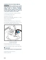
Page 21: ...brasive cleaner IMPORTANT_________________________ Never use abrasive cleaners to clean the equipment DISPENSER HANDLEASSEMBLYCLEANING Disassembly Use Drift Pin to push the Roll Pin from the Dispenser Handle Remove the Roll Pin using pliers Remove Dispenser Handle Spring Removing Roll Pin and Dispenser Handle Secure with Screw and Nut to ensure it stays together Rotate the top counter clockwise Re...

Page 22: ...e Use a flat edged tool to ensure the Seal is located correctly Position Seal with Flat Edged Tool Reassemble Piston to Dispenser Body Screw the Cap onto the body Ensure the Screw is positioned properly to allow internal components to align Reassemble Piston and Cap Insert spring in Dispense Handle Push in Plastic Insert and position with Screw Insert Spring and Position Plastic Insert Position Di...

Page 23: ...ut Vivreau s authorization When ordering components follow the instructions provided in the Illustrated Parts List Replacement procedures must be performed by an authorized service agent in accordance with all Federal State and Local Codes CHILLER COMPONENTS REMOVE THE CONDENSER FAN MOTOR WARNING Before performing any service involving electrical connection or disconnection and or exposure to elec...

Page 24: ... Unplug or isolate unit from the main power supply Failure to comply can cause property damage injury or death To perform this procedure proceed as follows Remove the rear Panel Rear Panel Removal Locate and loosen the two 2 crossbar support screws and move crossbar support off to the side Crossbar Support Screws Slide Chiller from cabinet to allow access to Thermostat Slide Chiller for Access to ...

Page 25: ... as follows Locate Agitator on top of Chiller unit Disconnect IEC Connector Disconnect the IEC Connector Loosen but do not remove four 4 Mounting Screws Slide Agitator to clear screw heads Lift and remove Agitator from Tank Loosen Four 4 Screws and Remove Agitator To replace Agitator reverse these steps Restore power to the unit WATER INLET SOLENOID REMOVAL WARNING Before performing any service in...

Page 26: ...lectrical connection or disconnection and or exposure to electrical components ALWAYS follow the Electrical LOCKOUT TAGOUT Procedure Unplug or isolate unit from the main power supply Failure to comply can cause property damage injury or death To perform this procedure proceed as follows Turn off Water Supply Valve Open Still Tap to relieve water pressure from line Open left side Panel Cover electr...

Page 27: ...de panel CARBONATOR LEVEL CONTROLLER REMOVAL WARNING Before performing any service involving electrical connection or disconnection and or exposure to electrical components ALWAYS follow the Electrical LOCKOUT TAGOUT Procedure Unplug or isolate unit from the main power supply Failure to comply can cause property damage injury or death To perform this procedure proceed as follows Open left side Pan...

Page 28: ...Water Supply Valve Close Valve on CO2 Tank Open Still and Sparkling Dispensers to relieve water pressure from the line Open left side Panel Cover electrical components with plastic sheet Pull and Twist Carbonator Relief Valve 1 4 turn This will lock the Valve in the open position Carbonator Level Probe Carbonator Level Probe Remove Wiring Harness from Probe Unscrew Probe and remove from Carbonator...

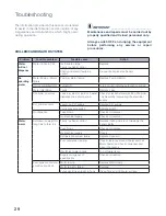
Page 29: ...ulty Replace Valve Controller timed out Leak in system or too much water dispensed in a short period Check for leaks before re setting Controller Achieved by interrupting the electrical supply CO2 alarm sounds Low or no CO2 supply Replace CO2 supply Faulty pressure switch Replace switch No dispense Fuse blown Check and replace No electrical supply Check and resolve Water warm Reduced ice weight or...

Page 30: ...on Seals Incorrect assembly post cleaning process Seals damaged or positioned incorrectly Re perform Dispensing Head Assembly and replace parts as required Water leaking from the green pipe on front of the unit Check Valve failure Debris in Vented Check Valve sited on the Carbonator Pump Strip and clean as per instructions contained in the Maintenance Section Low water supply flow Clogged Filter C...

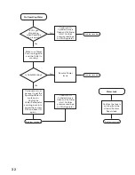
Page 31: ...l is frozen With Power ON open both Dispensers and continue to run Sparkling Water until Still Water dispenses This is the fastest and only way to thaw the Still Water Yes Note If only CO2 dispenses there is a water supply issue Confirm that Water Supply Valve to unit is Open and working before Dispatching ServiceTech Once water supply issue is resolved reset Carbonator Unplug the Chiller Carbonat...

Page 32: ...sure readings on CO2 Regulator Confirm CO2 Cylinder Valve is Open and Cylinder is full Confirm pressure readings on CO2 Regulator Make sure Power Cord is plugged in and the Outlet is working No Carbonator must be reset to get the Sparkling Water to work again Unplug the Chiller Carbonator and plug back in to power the system OFF and back ON again Problem resolved Problem resolved Is Outlet Working...

Page 33: ... Water Block Remove and bypass Water Block No No Is Still Water slower than normal Is water restored Yes No No Problem resolved Carbonator must be reset to get the Sparkling Water to work again Unplug the Chiller Carbonator and plug back in to power the system OFF and back ON again Sanitize and replace Filter Yes Problem resolved Problem resolved ...

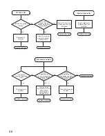
Page 34: ...Dispensing Temperature Is the Condenser Grille clogged or obstructed No Yes Clean the Condenser Grille with a Soft Brush or Cloth and remove any obstructions to the airflow Problem resolved Problem resolved Problem resolved Once unit is powered ON it may take up to 45 minutes for the water to dispense cold and 4 6 hours to maintain a cold Dispensing Temperature Problem resolved Yes Yes Yes Yes Con...

Page 35: ...FF 2 Touch and Hold the Sparkling Button until only Gas is dispensed 3 Release the Button and turn the Cleaning Mode Switch back ON 4 Let the unit cycle for 30 seconds and check the Sparkling Water again Replace CO2 Cylinder and or make sure CO2 Cylinder Valve and Secondary Shutoff Valve if equipped are open Yes Is the Sparkling Water OK Yes Problem resolved Is the Sparkling Water OK Yes ...

Page 36: ...nsing either Still or Sparkling Water Open CO2 Cylinder and or Secondary Shutoff Valve Problem resolved Check CO2 Pressure Switch and change if needed Problem resolved Problem resolved Check for faulty Agitator Problem resolved Check Refrigeration System Problem resolved Problem resolved Confirm Water Supply Valve is fully open before checking for a clogged Filter Problem resolved Unit makes Loud ...

Page 37: ...ste Yes No No Sanitize and replace Filter WaterTastes Bad Yes Does only Sparkling Water have a bad taste Yes Is the issue resolved Bad CO2 Cylinder Turn OFF the Power Switch on the back of the unit and dispense Sparkling Water until only CO2 is dispensed Turn OFF the CO2 Cylinder and dispense Sparkling Water to release all CO2 pressure Replace CO2 Cylinder and open Valve dispense the Sparkling Wat...

Page 38: ...ll replaceable parts Illustrations Item numbers on illustrations correspond with parts listings on pages that accompany the drawings Notes are included on illustrations where needed Parts Listings Parts listings identify serviceable parts with the following categories Item corresponds with numbers on illustrations for part identification Description specifies part name or description of the item Q...

Page 39: ... 2 IMI 06 0 290 122 Agitator 3 N A Compressor Capacitor 4 N A Compressor 120 V 5 N A Compressor Start Relay 6 58 1174 007 Thermostat 7 Level Sensor Float Switch Waste Water Catch Bin 8 58 0446 245 LED Indicator 9 CO2 REG KIT Co2 Regulator 10 N A Co2 Pressure Switch 11 FLOW REG 3 8 Flow Control NS 06 0 194201 Fan Motor 120 V NS Not Shown 1 2 3 4 and 5 11 6 7 8 9 10 ...

Page 40: ...484 Power control board 13 CARB PUMP Brass Pump 14 CARB MOTOR Carbonator Pump Motor 1 3 hp 120 V 15 N A Carbonator Level Probe 16 3M 56133 03 Water Filter Cartidge 17 58 0400 331 Water Inlet Solenoid 120 V NS TAP SS Water Tap NS TAP N02 1M1 Tap Nozzle NS TAP LENS ST L Tap Label Water Still NS TAP LENS SP L Tap Label Sparkling Water NS Not Shown 16 17 13 14 15 12 ...

Page 41: ...41 ...

Page 42: ...UE LEAD CATHODE 2 CARBONATOR LED CATHODE 3 CO2 PRESSURE LED CATHODE 4 WASTE LEVEL LED CATHODE 5 COMMON LED ANODES 6 BUZZER A 7 BUZZER B 8 WASTE LEVEL PROBE 9 WASTE LEVEL COMMON GROUND ELECTRONICS HOUSING EVO 50 CAPACITOR SOLENOID PUMP EVO 50WIRING SCHEMATIC POWER POWER SWITCH COMPRESSOR CONDENSER FAN ICE BANK T STAT AGITATOR TERMINAL BLOCK POWER INPUT L N L L N CARBONATOR BOWL LED PCB FLOAT SWITCH...

Page 43: ...43 Contact Info Phone Number 1 877 999 1044 Email InfoUSA vivreau com InfoCanada vivreau com Or visit vivreauwater com ...

Reviews: