VXO4841DBF
INSTALLATION GUIDE
PAGE 2 of 5
COMPRESSOR
MOUNTING
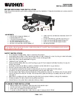
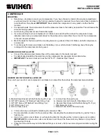
Determine a dry place to mount your compressors. If you have chosen to install in the engine compartment,
you should mount it as close to the front as possible to allow for maximum flow of air around them and also to
avoid heat from the exhaust.
IMPORTANT
: Never attach the compressors to any plastic or other flexible
material.
For optimal results, the compressors should be placed as close to the battery as possible. This will reduce the
amount of wiring needed.
Avoid placing compressors near flammable liquids.
I
f you are planning to move compressor’s air intake to an area other than where the compressors were
installed, make sure your placement allows for the airlines to be routed from the air inlet of the compressors
to the remote inlet air filters.
Mark the spots for the holes with the mounting base as a guide and then drill. Make sure both compressors
are secured.
To enhance performance and make sure the battery of your vehicle doesn’t discharge, keep the engine
running while the compressor is being used.
BRAIDED HOSE INSTALLATION
Connect the
stainless steel braided hose of the compressor to the tank’s inlet port.
For details about installing the water trap on the compressor line see water trap section below.
IMPORTANT
: T
he tank’s inlet port must be 3/8" N.P.T. (National Pipe Thread).
REMOTE AIR FILTER INSTALLATION KIT
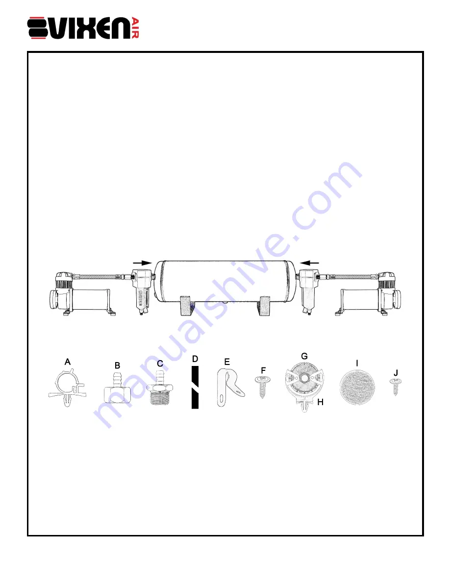
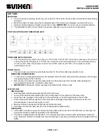
Only use if you need to move compressor’s air intake to an area other than where the compressor was installed.
A. Braided Hose Bracket with Self-Anchoring Pin (1 pc)
B. 3/8" NPT Female x 3/8" Barbed Tube Fitting (1 pc)
C. 3/8" NPT Male x 3/8" Barbed Tube Fitting (1 pc)
D. 3/8" OD Air Line (1 pc)
E. Air Line Clips (3 pcs)
F. Air Line Clips Screws (3 pcs)
G. Remote Inlet Air Filter with Filter Element (1 pc)
H. Remote Filter Holder with Self-Anchoring Pin (1 pc)
I. Filter Elements (2 pcs)
J. Remote Filter Holder Screws (2 pcs)
10 feet of air line is enclosed for attaching the remote air filter.
Find an installation location for the remote air filter, ensuring that the location should be dry and far from a
heat source.
Use a hose cutter, a razor blade, or a sharp knife when trimming the airline. A clean, square cut is optimal.
IMPORTANT
: Do not use wire cutters or scissors to cut the air line, these tools may flatten or crimp the air
line causing it to leak.
Place the airline all the way onto the barbed fittings or at least, until it covers two ridges and starts routing the
air line.


