VXO4841DBF
INSTALLATION GUIDE
PAGE 4 of 5
ELECTRICAL CONNECTION
COMPRESSOR
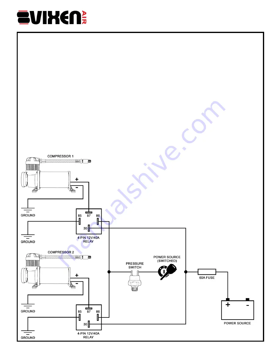
Red wire (positive) of the compressor is connected to
PIN 87
on the relay.
IMPORTANT
: Make sure to use
wire that is as heavy as the wire of the compressor
Black wire (negative) of the compressor and
PIN 85
of the relay are connected to ground.
Repeat above steps for the second compressor.
Connect together
PIN 86
of both relays and then connect it to one of the terminal of the pressure switch.
Attach the remaining terminal of the pressure switch to a power source in the vehicle that only gets power
when the vehicle’s ignition is on. Recommended connection points are: windshield wiper motor, blower motor
or an accessory terminal on the fuse panel. Make sure to use wire that is as heavy as the wire of the
compressor.
Connect together
PIN 30
of both relays and connect it to a constant power source using the provided 60A
fuse.
Both compressors are now set for use and will turn on automatically when air pressure in the air tank falls.
When air pressure reaches maximum PSI, they will turn off. If compressors fails to reach the maximum air
pressure of the tank, which is the Pressure Switch's cut OFF pressure, check all air connections for leaks.
While compressor are pumping, use soapy water or any bubble solution to perform this check. In case the
leak remains after tightening, re-apply thread sealant.
NOTE
: To makes installation fast, trouble free and professional, this kit comes with two Pre-wired Relay Plugs
(one for each relay), they will attach to the relay only in one position.


