background image

VIZIO L30e User Guide 

Version - 2/17/2005 

39 

www.vizioce.com 


4.3 - Telephone & Technical Support  

Products are often returned due to a technical problem rather than a defective product that may 
result in unnecessary shipping charges billed to you. Our trained support personnel can often 
resolve the problem over the phone. For more information on warranty service or repair, after the 
warranty period, please contact our Support Department at the number below.  
 
Quality service and consistent technical support are integral parts of V's commitment to service 
excellence. V's service representatives are dedicated to assist you with the utmost in customer 
satisfaction. To better assist you, please call toll free or contact us via email.  
 

Tel: (714) 668-0588, 7:30 am-5:30 pm PST Mon - Fri 

E-mail: techsupp@vinc.com 

VIZIO 

320A Kalmus Drive  

Costa Mesa, CA 92626  

Tel: (714) 668.0588 Fax: (714) 668-9099  

Web: 

www.vizioce.com


4.4 - Compliance 

Caution: Always use a power cable that is properly grounded. Please use the AC cords listed 
below for each area.  
 
 USA 

UL 


 Canada CSA 


 Germany VDE 
 Britain  BASE/BS 


Japan 

Electric Appliance Control Act  

4.5 - FCC Class B Radio Frequency Interference Statement 

NOTE: This equipment has been tested and found to comply with the limits for a Class B digital 
device, pursuant to Part 15 of the FCC Rules. These limits are designed to provide reasonable 
protection against harmful interference in a residential installation. This equipment generates, 
uses and can radiate radio frequency energy, and if not installed and used in accordance with the 
instructions, may cause harmful interference to radio communications. However, there is no 
guarantee that interference will not occur in a particular installation. If this equipment does cause 
harmful interference to radio or television reception, which can be determined by turning the 
equipment off and on, the user is encouraged to try to correct the interference by one or more of 
the following measures:  

1.  Reorient or relocate the receiving antenna.  
2.  Increase the separation between the equipment and receiver.  
3.  Connect the equipment into an outlet on a circuit different from that to which the receiver 

is connected.  

4.  Consult the dealer or an experienced radio/TV technician for help.  

 
Notice: 

1.  The changes or modifications not expressly approved by the party responsible for 

compliance could void the user’s authority to operate the equipment. 

2.  Shielded interface cables and AC power cord, if any, must be used in order to comply 

with the emission limits. 

3.  The manufacturer is not responsible for any radio or TV interference caused by 

unauthorized modification to this equipment.  It is the responsibilities of the user to 
correct such interference. 

Summary of Contents for L30e

Page 1: ......

Page 2: ... RGB Video 20 2 4 Connecting Your VCR or Video Camera 20 2 5 Connecting Coaxial RF 21 2 5 1 Using Your Antenna or Cable TV 21 2 5 2 Using the Antenna through Your VCR 21 2 6 Connecting External Amplified Speakers 22 2 7 Connecting an External Receiver or Amplifier 23 2 8 Connecting a Computer 24 Chapter 3 Getting Started 25 3 1 Turning your LCD TV On and Off 25 3 2 Preparing the LCD for Wall Mount...

Page 3: ... 500 1 typical Viewing Angle 170 horizontal 170 vertical for CR 10 Inputs 1 x S Video 2 x Component Video YPbPr 2 x Component Audio In right left 1 x Analog RGB D Sub 15 pin 1 x RGB Audio 1 x DVI D 1 x DVI Audio in 1 x RF for internal NTSC tuner 2 x AV Composite Video 2 x AV Audio In right left Output 1 x Stereo mini jack for headphones 1 x Audio right left Features PiP POP Noise Reduction 3 2 Pul...

Page 4: ...ipping needs 1 4 Installation Please read the user manual carefully before performing the installation The power consumption of the display is approximately 180 watts significantly higher than a typical television Please use the power cord designated for the product When an extension cord is required use one with the correct power rating The cord must be grounded and the grounding feature must not...

Page 5: ...y into a grounded power outlet as a safety feature If your outlet does not accommodate the three wire plug have an electrician install the correct outlet or use an adapter to ground the appliance safely Do not defeat the safety purpose of the grounded plug Do not overload power strips and extension cords Overloading can result in fire or electric shock The wall socket shall be installed near the e...

Page 6: ...h regard to proper grounding of the mast and supporting structure grounding of the lead in wire to an antenna discharge unit size of the grounding conductors location of antenna discharge unit connection to grounding electrodes and requirements of the grounding electrode Lightning Protection For added protection of the LCD TV during a lightning storm or when it is left unattended or unused for lon...

Page 7: ...e LCD TV VIZIO Universal Remote Control Power Cord Audio Cable red and white Quick Setup Guide This User Guide IMPORTANT Save the original box and all the packing material for future shipping needs Note Your product may also include various other accessories depending on region of purchase ...

Page 8: ... sequence TV AV1 AV2 S Video YPbPr1 YPbPr2 VGA and DVI Once you have stepped through the entire sequence you will return to the beginning 5 Power Button Switch the TV on by pressing the button once The indicator light above the power button will be blue Press the button again to turn the TV off 6 Remote Control Sensor This is the window that passes all of the remote signals to the sensor Point the...

Page 9: ...yer or set top box These connectors are indicated by the blue band 7 S Video 1 Connect the S Video to external video device such as VCR DVD and video games These connectors are indicated by the red band 8 AV 1 Connect the Composite video to external video device such as VCR DVD and video games These connectors are indicated by the yellow band 9 AV Audio In Right and Left R L Connect the external a...

Page 10: ...ote Control is a comprehensive remote that can be used to control up to four different components The remote control button functions are explained on the following pages VIZIO Universal Remote Control Button Description 8 9 1 22 19 21 10 14 16 25 28 31 32 35 36 17 4 5 6 2 3 7 12 11 13 15 18 20 23 24 26 27 29 30 33 34 ...

Page 11: ...is button enters a channel number greater than 100 in TV mode Additionally it works as an ENTER button in other video modes 11 VOL or These buttons turn volume up or down 12 LAST This button recalls the previously viewed channel 13 INPUT This button changes the input source 14 CH or These buttons change the channels up or down 15 WIDE GUIDE This button cycles through standard and widescreen viewin...

Page 12: ...onent is activated with the remote control Additionally this button will select the Y2 Pb2 Pr2 component in TV mode for the VIZIO L30e 26 ZOOM Use this key to zoom the image in or out Note This button is not functional for the L30e 27 Swap Used to swap the inputs from the main screen PiP or POP picture mode 28 SubCh These buttons are used to select the channels within the PIP Note The SubCh is not...

Page 13: ...attach the battery cover Precautionary Tips for Inserting the Batteries Only use the specified AA batteries Do not mix new and old batteries This may result in cracking or leakage that may pose a fire risk or lead to personal injury Inserting the batteries incorrectly may result in cracking or leakage that may pose a fire risk or lead to personal injury Dispose of the batteries in accordance with ...

Page 14: ... VIZIO Universal Remote Control The remote control should be kept dry and away from heat sources Avoid humidity If the display responds erratically to the remote control or does not respond at all check the batteries If the batteries are low or exhausted replace them with fresh batteries When not using the remote control for a long period of time remove the batteries Do not take apart the batterie...

Page 15: ...nto two signals one containing the black and white information and the other containing the color information Separating the color in this way avoids cross color effects where closely spaced black and white lines are erroneously displayed in color It also enables text to be displayed more sharply Better Component The video signal is separated into three signals one containing the black and white i...

Page 16: ...cable to the DVI output of your DVD player and the other end to the DVI input in the rear of your LCD TV 3 Connect the Audio on your DVD player to the DVI Audio In next to the DVI In connection in the rear of your LCD TV 4 Turn on the power to the LCD TV and your DVD player 5 Select DVI using the INPUT button on the front of the LCD TV Note a The DVI input on your LCD TV supports High bandwidth Di...

Page 17: ...o the corresponding Pr1 red color connector in the rear of your LCD TV 5 Connect the R red color and L white color audio connectors on the rear of your DVD player to the R red color and L white color audio input connectors in the rear of your LCD TV 6 Turn on the power to the LCD TV and DVD player 7 Select YPbPr using the INPUT button on the front of the LCD TV Note a Refer to your DVD player user...

Page 18: ... rear of your LCD TV 3 Connect the R red color and L white color audio connectors on the rear of your DVD player to the R red color and L white color audio input connectors in the rear of your LCD TV 4 Turn on the power to the LCD TV and DVD player 5 Select S Video using the INPUT button on the front of the LCD TV Note Refer to your DVD player user manual for more information about the video outpu...

Page 19: ...o the R red color and L white color audio input connectors in the rear of your LCD TV 4 Turn on the power to the LCD TV and DVD player 5 Select AV1 using the INPUT button on the front of the LCD TV Note a If you are already using the AV1 input for another component or you do not want to use the AV1 input for the DVD player you can connect the DVD player to the AV input using the side connections o...

Page 20: ...end to the DVI input in the rear of your LCD TV 3 Connect the Audio Out on your HDTV Set Top Box to the DVI audio connectors R red color and L white color on your LCD TV 4 Turn on the power to the LCD TV and your HDTV Set Top Box 5 Select DVI using the INPUT button on the front of the LCD TV Note a Use TMDS signals conforming to DVI standards The TMDS input is a single link input b To maintain the...

Page 21: ...on 1 Turn off the power to the LCD TV and VCR or video camera 2 Connect the S Video jack on your VCR or video camera to the S Video1 jack in the rear of your LCD TV 3 Connect the R red color and L white color audio connectors on your VCR or video camera to the R red color and L white color audio input connectors in the rear of your LCD TV 4 Turn on the power to the LCD TV and VCR or video camera 5...

Page 22: ...our VCR Installation 1 Turn off the power to the LCD TV and VCR 2 Connect the Output to TV RF Out or Antenna Out connector on the rear of your VCR to the RF connector on the rear of your LCD TV 3 Turn on the power to the LCD TV and VCR 4 Select TV using the INPUT button on the front of the LCD TV 5 Select Channel 3 or 4 to match the channel selected on the rear of your VCR Note See page 30 for sel...

Page 23: ...he R red color and L white color audio output connectors in the AUDIO OUT connections in the rear of your LCD TV 3 Turn on the power to the LCD TV and speakers 4 Press the MENU button on the remote control to activate the on screen display OSD 5 Press the f on the remote control until AUDIO SETTINGS is highlighted 6 Press the d on the remote control to select SPEAKER 7 Press the f on the remote to...

Page 24: ...R red color and L white color audio connectors on the rear of your receiver or amplifier to the R red color and L white color audio output connectors in the AUDIO OUT group on the rear of your LCD TV 3 Turn on the power to the LCD TV and receiver or amplifier 4 Turn on the power to the LCD TV and speakers 5 Press the MENU button on the remote control to activate the on screen display OSD 6 Press t...

Page 25: ...Out on your computer to the Audio In next to the VGA Input in the rear of your LCD TV 4 Turn on the power to the LCD TV and your computer 5 Select VGA using the INPUT button on the front of the LCD TV Note a If connecting to a PC RGB DVI set LCD TV timing mode to VESA 1280x768 at 60Hz for best picture quality refer to the graphic card s user guide for questions on how to set this timing mode b Ref...

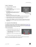
Page 26: ...or best picture quality refer to the graphic card s user guide for questions on how to set this timing mode 3 2 Preparing the LCD for Wall Mounting The VIZIO L30e can either be kept on the base stand or mounted to the wall for viewing If you would like affix your television to the wall a mount can be purchased through www vizioce com or at a local consumer electronic retailer If you choose to moun...

Page 27: ...ached TV Channels To step up through the available TV channels press the CH button on the front panel or remote control once for the next channel or hold it depressed until the desired channel is reached To step down through the available TV channels press the CH button on the front panel or remote control once for the previous channel or hold it depressed until the desired channel is reached Wide...

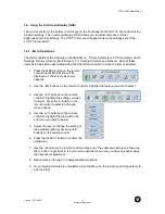
Page 28: ...he Main Menu will be displayed on the screen as shown opposite 2 Use the e f buttons on the remote control to highlight the feature you wish to select 3 Use the c d buttons on the remote control to highlight the setting you wish to adjust Press the f button on the remote control to enter into the sub menu options 4 Use the c d buttons on the remote control to highlight the area within the sub menu...

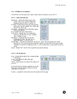
Page 29: ...k or user Sharpness Adjust the amount of detail enhancement Note this option is not selectable when TV is in PC mode Aspect Ratio Choose from Standard Fill or Zoom Note Since the aspect ratio of the television is 15 9 you will see small black bars at the top and bottom of the screen while watching 16 9 content in Standard mode To remove these bars simply switch to the Fill mode Reset Resets the TV...

Page 30: ...isplays selected Sub Screen within the main screen POP Displays selected Sub Screen next to the main screen at the same size Main Source Selects Main Screen sources from the following TV AV1 AV2 S Video SV2 YPbPr1 YPbPr2 VGA and DVI PiP Source Selects Sub Screen sources from the following TV AV1 AV2 S Video SV2 YPbPr1 YPbPr2 VGA and DVI Swap Changes the PIP screen to the main screen and consequent...

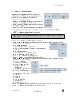
Page 31: ...V1 X X X AV2 X X X S Video X X X YPbPr1 X X X X X X YPbPr2 X X X NTSC Tuner X X X X Input source is available Blank Input source is not available 3 4 2 5 Channel Settings TV CATV Selects the TV source type from the following Antenna Cable STD Auto Scan Automatically detects the available TV channels Channel Edit Manually add and delete selected channels Close Caption Turn the close caption OFF or ...

Page 32: ...children 13 years of age and older R mature audience NC 17 no one under 17 years of age X Adult audience only TV PG Rating Options include the following TVY all children TV Y7 older children TV G general audience TV PG guidance suggested TV 14 strongly cautioned TV MA mature audience You can also customize these ratings for Fantasy Violence Sexual situations Foul language Suggestive dialog All Not...

Page 33: ... Password Edit 6 Enter your old password 7 Then enter your new password 8 Enter the new password again in the Confirm area 9 Press the ENTER button repeatedly to exit the OSD 3 4 2 7 General Settings Menu Position Changes the OSD horizontal vertical position adjustment Menu Timeout Adjusts the time to turn OFF the OSD Language Changes the OSD language Sleep Timer Sets the sleep timer in 30 minute ...

Page 34: ...lock or unblock You can select from the following ratings G General audience PG Parental guidance suggested PG 13 Recommended for children 13 years of age and older R mature audience NC 17 no one under 17 years of age X no one under 17 years of age 9 Press button until TV Rating is highlighted 10 Press the SELECT button to open the TV Rating menu 11 Press the buttons to select which rating you wan...

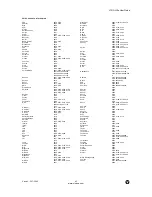
Page 35: ...control at the TV and press the POWER button The TV will turn off 3 5 1 2 Programming for VCR 1 Manually turn on the VCR 2 Press the VCR button on the remote control 3 Press and hold the SETUP button until the LED LIGHT flashes twice 4 Find the programming code for your VCR in the code list in the back of this book and enter it using the Number Buttons If the code is accepted the LED flashes twice...

Page 36: ...the LED LIGHT flashes twice 4 Find the programming code for your DVD player in the code list in the back of this book and enter it using the Number Buttons If the code is accepted the LED flashes twice after the last digit is entered If the LED does not flash twice repeat Steps 2 through 4 with the next code listed for the component and manufacturer 5 Point the remote control at the DVD Player and...

Page 37: ...assign the component buttons on the remote control if you have more than one of the same types of component For example if you are using the remote to control the cable CBL CD DVD TV and two VCRs you can reassign the AV2 button as a second VCR button To reassign component buttons 1 Press and hold the SETUP button until the LED flashes twice 2 Press 9 9 2 The LED flashes twice 3 Press the component...

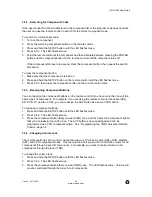
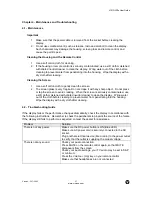
Page 38: ... avoid cracking When the screen is seriously contaminated use a soft cloth moistened with diluted neutral cleaner to clean the display Wring water out of the cloth before cleaning to prevent water from penetrating into the housing Wipe the display with a dry cloth after cleaning 4 2 Troubleshooting Guide If the display fails or the performance changes dramatically check the display in accordance w...

Page 39: ...ries are inserted correctly Batteries could be weak Duplicate or Ghost channels located during scan Use the Channel EDIT function to DELETE duplicate or unwanted channels from the database of active channels There appears to be image quality issues TV For best image quality Standard Definition TV should be viewed as 4 3 COMPONENT 480i For best image quality the YCbCr Input should be used Tips for ...

Page 40: ... B digital device pursuant to Part 15 of the FCC Rules These limits are designed to provide reasonable protection against harmful interference in a residential installation This equipment generates uses and can radiate radio frequency energy and if not installed and used in accordance with the instructions may cause harmful interference to radio communications However there is no guarantee that in...

Page 41: ...egrated in the set Integrated HDTV An HDTV that has the digital tuner built into the set It does not need a separate set top box to receive over the air DTV signals Plug and Play or Digital Cable Ready A DTV or other device for digital cable customers that plugs directly into the cable jack and does not require a separate set top box Plug and Play TV owners must obtain a CableCARD from their cable...

Page 42: ... 0019 0007 Optimus 0021 Panasonic 0000 0107 0021 Paragon 0000 Philips 0153 Pioneer 0144 0533 0877 Popular Mechanics 0400 Pulsar 0000 Quasar 0000 RCA 0021 RadioShack 0015 0315 0797 0883 Recoton 0400 Regal 0020 0259 Regency 0002 Rembrandt 0011 Runco 0000 SLMarx 0040 Samsung 0144 0040 Scientific Atlanta 0008 0477 0017 0877 Signal 0015 0040 Signature 0011 Sprucer 0021 Starcom 0003 0015 Stargate 0015 0...

Page 43: ...0195 NAD 0320 Nakamichi 0097 Onkyo 0135 Optimus 0531 0670 0186 0080 0042 0181 0219 0738 0801 1023 Panasonic 0039 0309 Penney 0195 Philips 0189 0391 Pioneer 0531 0014 0150 0630 0080 1023 Quasar 0039 RCA 0531 0054 0360 Realistic 0195 0181 Sansui 0189 Sanyo 0219 0801 Sharp 0186 Sherwood 0491 0502 Sony 0158 0474 Soundesign 0670 Teac 0463 Technics 0039 0309 Victor 0074 Wards 0158 0014 0189 0080 0054 Ya...

Page 44: ...shita 0250 Megatron 0178 0145 Memorex 0154 0250 0463 0150 0178 0056 0016 Midland 0047 0017 0051 0039 Minutz 0021 Mitsubishi 0093 0150 0178 0019 Motorola 0093 Multitech 0180 NAD 0156 0178 0166 NEC 0030 0019 0056 NTC 0092 Nikko 0030 0178 0092 Onwa 0180 Optimus 0154 0250 0166 Optonica 0093 0165 Orion 0236 0463 0179 Panasonic 0051 0250 Penney 0047 0156 0051 0060 0030 0178 0021 0019 0056 0039 1347 Phil...

Page 45: ... NEC 0104 0067 0041 0038 Nikko 0037 Noblex 0240 Olympus 0035 Optimus 0037 0048 0104 0162 0454 1062 1162 1262 Orion 0184 0209 0002 Panasonic 0035 0162 0225 0454 1062 1162 1262 Penney 0035 0037 0240 0042 0038 Pentax 0042 Philco 0035 0209 Philips 0035 0081 Pilot 0037 Pioneer 0067 Profitronic 0240 Proscan 0060 Protec 0072 Pulsar 0039 Quarte 0046 Quartz 0046 Quasar 0035 0162 0454 1162 RCA 0060 0035 004...

Page 46: ...per servicing tampering or normal wear and tear or TVs on which the serial number has been removed or defaced Image Sticking caused by operating at excessive brightness levels for extended periods or mishandling are not covered by this warranty ANY IMPLIED WARRANTIES INCLUDING ANY IMPLIED WARRANTY OF MERCHANTABILITY AND FITNESS FOR A PARTICULAR PURPOSE SHALL BE LIMITED IN DURATION TO THE PERIOD OF...

Page 47: ......

Reviews: