background image

VZN T5 SERIES

13

P/N 1011066 Rev. G 12/13 

INSTALLATION (continued)

Rinsing the Ultra Filter Cartridge

The Ultra Filter Cartridge comes pre-installed in the VZN  

system. The Ultra Filter Cartridge must be rinsed before the 

system is used to remove any air and protective solution.

NOTE: Ultra Filter Cartridge must be rinsed to drain 

before use. Rinsing to drain removes storage solution 

and air. Do NOT rinse into carbon if present. Carbon life 

and/or performance may be affected.

NOTE: Make sure the Carbon Element and TAC Cartridge, 

if present, are NOT installed. These should only be 

installed after the Ultra Filter Cartridge has been rinsed.

  1.  Direct water from the Rinse Ball Valve to a drain.

  2.  Close the Outlet Ball Valve.

  3.  Close the Inlet Ball Valve.

  4.  Open the Rinse Ball Valve.

  5.  Slowly turn on the water supply to the VZN system.

  6.  Slowly open the Inlet Ball Valve. Air and water will come 

out of the Rinse Ball Valve.

  7.  Press the 

FLUSH

 button. The Drain Valve will open and 

air and water will come out of the drain line. Repeat six 

times to ensure all air and storage solution are flushed 

out of the Ultra Filter Cartridge.

  8.  Continue to allow water to run at full flow out of the 

Rinse Ball Valve for at least 15 minutes.

  9.  After 15 minutes, close the Rinse Ball Valve and allow 

the system to sit for 15 minutes without any water 

flow to release any trapped air from the Ultra Filter 

Cartridge.

  10.  Inspect the unit for any leaks, repairing as needed.

  11.  After 15 minutes, open the Rinse Ball Valve and wait for 

five minutes to flush out any remaining air.

  12.  Close the Rinse Ball Valve and disconnect the garden 

hose.

  13.  Press the 

FLUSH

 button to open the Drain Valve. 

Repeat six times to ensure any remaining air is flushed 

out of the system.

  14.  Open the closest downstream tap or faucet.

  15.  Slowly open the Outlet Ball Valve and allow water to run 

through the system and out the faucet for five minutes.
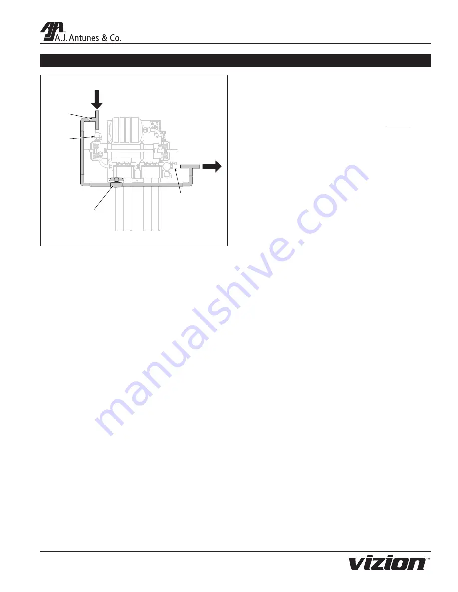
Water

Flow

Inlet Ball

Valve

(Manual)

Fully

Ported

Ball Valve

Tee

Water

Flow

Outlet Ball

Valve

(Manual)

Figure 7. Install Bypass

Installing a Bypass

It is recommended that an optional bypass be installed to help 

with replacing cartridges and servicing the system. Installation 

of a bypass can be done easily as the Inlet and Outlet Ball 

Valves are already installed.

  1.  Install tees on the end of the plumbing leading to the 

Inlet and Outlet Ball Valves.

  2.  Connect the two tees by installing plumbing and a fully 

ported (preferably 3/4”) Ball Valve.

  3.  When the system is in use, open the Inlet and Outlet 

Ball Valves and close the Bypass Ball Valve.

  4.  When servicing is needed, close the Inlet and Outlet Ball 

Valves and open the Bypass Ball Valve.

Starting the Controller

  1.  Select the proper AC plug for your electrical outlet and 

install it onto the power supply.

  2.  Plug the appropriate end of the power cord into the 

controller.

  3.  Plug the other end of the power cord into the electrical 

outlet. The LEDs on the controller will light up.

  4.  The controller automatically enters Flush Mode and the 

Flush LED starts to flash.

  5.  When flushing is complete, the Flush LED will stop 

flashing and one or more LEDs will remain lit, indicating 

the unit has power and which interval is selected in the 

controller.

Summary of Contents for VZN-421H-T5

Page 1: ...y NSF International and WQA against NSF ANSI Standard 42 and 53 for the reduction of Standard No 42 Aesthetic Effects Nominal Particulate Reduction Class I Standard No 53 Health Effects Cyst Reduction...

Page 2: ...nt or damage as result of improper use Installation of electrical service Normal maintenance as outlined in this manual Malfunction resulting from improper maintenance Damage from moisture leaking int...

Page 3: ...olumn and have it handy when calling for assistance The serial number is on the specification plate located on the system OWNER INFORMATION continued IMPORTANT A J Antunes and Company reserves the rig...

Page 4: ...ll electrical connections must be in accordance with local electrical codes and any other applicable codes WARNING ELECTRICAL SHOCK HAZARD FAILURE TO FOLLOW THESE INSTRUCTIONS COULD RESULT IN SERIOUS...

Page 5: ...eaning solutions insecticides Protect from abrasive material The membranes must be protected from abrasive materials like shavings left in a pipe Abrasive materials in contact with the membrane can ca...

Page 6: ...08 50 60 VZN 441H T5 9700750 100 240 10 08 50 60 Electrical Cord Plug Configurations Kit Model Number Description Configuration 0012146 DC Power Supply 100 240 VAC Includes the 4 plug adaptors below N...

Page 7: ...ary NOTE The NSF WQA information provided applies to the Ultra Filter cartridge Do not use with water that is microbiologically unsafe or of unknown quality without adequate disinfection before or aft...

Page 8: ...llecting on the membrane wall The Drain Valve is only powered during Flush Mode NOTE Do NOT unplug the power cord or turn off the sys tem during Flush Mode If there is a power outage or the system is...

Page 9: ...atch the appropriate outlet Do NOT connect the system to a switched electrical outlet PLUMBING NOTE The system must be connected to the COLD water line Do NOT connect the system to the hot water line...

Page 10: ...the system to the wall Some of the bottom mount INSTALLATION continued ing holes may be obscured Plan your mounting accordingly Follow these steps to secure the Mounting Bracket to the wall and seat...

Page 11: ...with an appropriate fitting not supplied Figure 3 3 Direct the other end of the hose to the drain Figure 3 When connecting the drain hose pay attention to the follow ing guidelines The drain line plum...

Page 12: ...gure 6 Do NOT overtighten fittings as this could cause the plastic ball valve to crack Use plastic fittings and a pipe thread sealant approved for use on PVC fittings when making connections Filtered...

Page 13: ...and wait for five minutes to flush out any remaining air 12 Close the Rinse Ball Valve and disconnect the garden hose 13 Press the FLUSH button to open the Drain Valve Repeat six times to ensure any r...

Page 14: ...e system until the presence of sanitizer is gone 14 Open all other faucets and taps in line with the system to flush any remaining sanitizer from the plumbing 15 Close all faucets and taps Rinsing the...

Page 15: ...ght coating of lubricant to the inside cen ter tube at both ends of the new cartridge 10 Record the serial number of the new cartridge The cartridge serial number is engraved on one end of the outer t...

Page 16: ...ining the Carbon Element into place on the Carbon Element Head The Housing will come to a hard stop at the end of the thread Use a Filter Wrench if necessary NOTE Do NOT overtighten the Carbon Element...

Page 17: ...The Housing will come to a hard stop at the end of the thread Use a Filter Wrench if necessary 10 Direct water from the Rinse Ball Valve to drain NOTE It is important to direct the Rinse Ball Valve t...

Page 18: ...will also turn on Figure 12 Universal Pulse Controller Semi Annual Tasks Check Permeate Tank Air Pre Charge It is recommended the permeate tank air charge be checked every six months Tools and suppli...

Page 19: ...replace the outlet check valve assembly The inlet flow restrictor may be plugged Clean or replace the inlet flow restrictor Water tastes bad Carbon Element need replacing Replace Carbon Element Stora...

Page 20: ...SERIES 20 P N 1011066 Rev G 12 13 REPLACEMENT PARTS 30 36 37 33 25 25 1 2 39 3 31 12 28 20 14 14 29 16 32 38 14 15 19 4 5 6 7 8 9 11 17 21 13 26 27 18 20 21 22 23 24 24 35 9 8 10 10 34 VZN 421H T5 Sy...

Page 21: ...ES 21 P N 1011066 Rev G 12 13 30 33 25 1 2 3 31 34 12 20 16 32 14 15 19 4 5 6 7 8 9 11 17 21 13 18 20 21 22 23 24 9 8 10 10 36 37 25 28 14 14 29 26 27 24 35 39 38 REPLACEMENT PARTS continued VZN 441H...

Page 22: ...34 0505871 VZN Mounting Bracket 1 35 2190154 Adaptor 1 Stem 1 36 2180255 TAC 05 Housing and O Ring 1 37 7000554 TAC 05 Cartridge Kit 1 38 0021667 Flow Regulator Assy 7 9 gpm 1 39 0012146 Power Adapto...

Page 23: ...VZN T5 SERIES 23 P N 1011066 Rev G 12 13 NOTES...

Page 24: ...operating and maintenance instructions of this manual and or labor involved in moving adjacent objects to gain access to the Equipment 2 A J Antunes Co reserves the right to make changes in design or...

Reviews: