background image

VZN T5 SERIES

18

P/N 1011066 Rev. G 12/13

MAINTENANCE (continued)

Changing the Interval Setting

Resetting the Timer Program

During the normal operation, the system will flush accord-

ing to the set interval. It is possible the system will flush at a 

time of high water use. If this poses a problem, the controller 

can be reset. Unplug the power supply, wait for 5 seconds, 

and then plug the power supply in. When power is restored 

to the controller, it will automatically enter Flush Mode. The 

controller will then begin timing from the point when power is 

restored based on the interval setting selected.

Flush 

Interval

Button

Hold Time

Button 

LED

Flush  

LED

15 minutes

A

10 seconds

On

On

30 minutes

B

10 seconds

On

On

45 minutes

C

10 seconds

On

On

1 hour

A

5 seconds

On

Off

4 hour

B

5 seconds

On

Off

6 hours

C

5 seconds

On

Off

12 hours

D

5 seconds

On

Off

24 hours

D

10 seconds

On

On

CAUTION

Changing the flush interval can cause the Ultra Filter to 

plug prematurely and may reduce the life of the filter. 

Consult the factory for more information.

Though not recommended, the interval setting on the 

Universal Pulse Controller can be changed. If the setting must 

be changed, use the chart below. Press and hold the corre-

sponding button. After 5 seconds, the Button LED will turn on. 

After 10 seconds, the Flush LED will also turn on.

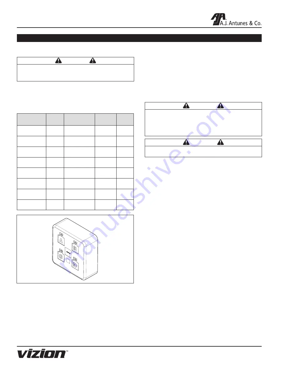
Figure 12. Universal Pulse Controller

Semi-Annual Tasks

Check Permeate Tank Air Pre-Charge

It is recommended the permeate tank air charge be 

checked every six months.
Tools and supplies required:

• 

Air Pressure Gauge, 5‒40 psi range (0.3‒2.7 bar) 

with tire valve (Schrader Valve) connection

CAUTION

Air pre-charge should only be checked and adjusted 

under zero system pressure. The system must be 

depressurized before checking the tank pre-charge. 

Do NOT adjust the tank air pre-charge with the system 

under pressure.

CAUTION

Be careful when adding air to the tank. Do NOT add too 

much air pressure to the tank.

•  Source of compressed air (manual bicycle tire 

pump or air compressor) 

1.  Refer to Figure 1. Depressurize the system by 

closing the Inlet and Outlet Valves and opening 

the Rinse Valve. Make sure the Permeate Tank is 

fully drained.

2.  Unscrew the protective cap from the air valve on 

the tank.

3.  Use the pressure gauge to check the tank pre-

charge for pressure. 

NOTE:

 If any water comes out the air valve, the tank  

bladder has ruptured and the tank needs to be 

replaced.

4.  The permeate tank should have a pressure of 28-

31 PSI.

•  To add pressure to the permeate tank, use a 

manual bicycle tire pump or other source of 

compressed air.

•  To release pressure from the permeate tank, 

press the center pin on the air inlet valve. 

5.  Once the permeate tank is at 28-31 PSI, replace 

the protective cap on the air valve.

6.  Pressurize system by closing the Rinse Valve and 

opening the Inlet and Outlet Valves.

Summary of Contents for VZN-421H-T5

Page 1: ...y NSF International and WQA against NSF ANSI Standard 42 and 53 for the reduction of Standard No 42 Aesthetic Effects Nominal Particulate Reduction Class I Standard No 53 Health Effects Cyst Reduction...

Page 2: ...nt or damage as result of improper use Installation of electrical service Normal maintenance as outlined in this manual Malfunction resulting from improper maintenance Damage from moisture leaking int...

Page 3: ...olumn and have it handy when calling for assistance The serial number is on the specification plate located on the system OWNER INFORMATION continued IMPORTANT A J Antunes and Company reserves the rig...

Page 4: ...ll electrical connections must be in accordance with local electrical codes and any other applicable codes WARNING ELECTRICAL SHOCK HAZARD FAILURE TO FOLLOW THESE INSTRUCTIONS COULD RESULT IN SERIOUS...

Page 5: ...eaning solutions insecticides Protect from abrasive material The membranes must be protected from abrasive materials like shavings left in a pipe Abrasive materials in contact with the membrane can ca...

Page 6: ...08 50 60 VZN 441H T5 9700750 100 240 10 08 50 60 Electrical Cord Plug Configurations Kit Model Number Description Configuration 0012146 DC Power Supply 100 240 VAC Includes the 4 plug adaptors below N...

Page 7: ...ary NOTE The NSF WQA information provided applies to the Ultra Filter cartridge Do not use with water that is microbiologically unsafe or of unknown quality without adequate disinfection before or aft...

Page 8: ...llecting on the membrane wall The Drain Valve is only powered during Flush Mode NOTE Do NOT unplug the power cord or turn off the sys tem during Flush Mode If there is a power outage or the system is...

Page 9: ...atch the appropriate outlet Do NOT connect the system to a switched electrical outlet PLUMBING NOTE The system must be connected to the COLD water line Do NOT connect the system to the hot water line...

Page 10: ...the system to the wall Some of the bottom mount INSTALLATION continued ing holes may be obscured Plan your mounting accordingly Follow these steps to secure the Mounting Bracket to the wall and seat...

Page 11: ...with an appropriate fitting not supplied Figure 3 3 Direct the other end of the hose to the drain Figure 3 When connecting the drain hose pay attention to the follow ing guidelines The drain line plum...

Page 12: ...gure 6 Do NOT overtighten fittings as this could cause the plastic ball valve to crack Use plastic fittings and a pipe thread sealant approved for use on PVC fittings when making connections Filtered...

Page 13: ...and wait for five minutes to flush out any remaining air 12 Close the Rinse Ball Valve and disconnect the garden hose 13 Press the FLUSH button to open the Drain Valve Repeat six times to ensure any r...

Page 14: ...e system until the presence of sanitizer is gone 14 Open all other faucets and taps in line with the system to flush any remaining sanitizer from the plumbing 15 Close all faucets and taps Rinsing the...

Page 15: ...ght coating of lubricant to the inside cen ter tube at both ends of the new cartridge 10 Record the serial number of the new cartridge The cartridge serial number is engraved on one end of the outer t...

Page 16: ...ining the Carbon Element into place on the Carbon Element Head The Housing will come to a hard stop at the end of the thread Use a Filter Wrench if necessary NOTE Do NOT overtighten the Carbon Element...

Page 17: ...The Housing will come to a hard stop at the end of the thread Use a Filter Wrench if necessary 10 Direct water from the Rinse Ball Valve to drain NOTE It is important to direct the Rinse Ball Valve t...

Page 18: ...will also turn on Figure 12 Universal Pulse Controller Semi Annual Tasks Check Permeate Tank Air Pre Charge It is recommended the permeate tank air charge be checked every six months Tools and suppli...

Page 19: ...replace the outlet check valve assembly The inlet flow restrictor may be plugged Clean or replace the inlet flow restrictor Water tastes bad Carbon Element need replacing Replace Carbon Element Stora...

Page 20: ...SERIES 20 P N 1011066 Rev G 12 13 REPLACEMENT PARTS 30 36 37 33 25 25 1 2 39 3 31 12 28 20 14 14 29 16 32 38 14 15 19 4 5 6 7 8 9 11 17 21 13 26 27 18 20 21 22 23 24 24 35 9 8 10 10 34 VZN 421H T5 Sy...

Page 21: ...ES 21 P N 1011066 Rev G 12 13 30 33 25 1 2 3 31 34 12 20 16 32 14 15 19 4 5 6 7 8 9 11 17 21 13 18 20 21 22 23 24 9 8 10 10 36 37 25 28 14 14 29 26 27 24 35 39 38 REPLACEMENT PARTS continued VZN 441H...

Page 22: ...34 0505871 VZN Mounting Bracket 1 35 2190154 Adaptor 1 Stem 1 36 2180255 TAC 05 Housing and O Ring 1 37 7000554 TAC 05 Cartridge Kit 1 38 0021667 Flow Regulator Assy 7 9 gpm 1 39 0012146 Power Adapto...

Page 23: ...VZN T5 SERIES 23 P N 1011066 Rev G 12 13 NOTES...

Page 24: ...operating and maintenance instructions of this manual and or labor involved in moving adjacent objects to gain access to the Equipment 2 A J Antunes Co reserves the right to make changes in design or...

Reviews: